2VGA - consolized retro portable game systems
Disclaimer : I’m a perfect dummy on electronics and FPGA. I’m a software not a hardware man. So anything in this document could be totally wrong ;) Feel free to correct me so I could learn !
07.02.2020 : first public release
12.02.2020 : added NES/SNES, N64, SMS, MD, PSX controller informations
10.05.2021 : some update on LCD technology and Wonderswan, + trying to make it easier to read with better formatting
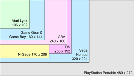
Portable game systems use LCD, each one with its own resolution, colors and refresh rate.
The main problem is that this LCD will fail whatever you do, it’s not a lifetime product.
Beware of the sun at all cost !
Since they are often specifically made for a device, no replacement exists and the device often finishes on eBay in the category “for parts”.
If you add to this that most of the first LCD screens had no backlight, a lot of people look for another way to play your games.
The most known alternative is emulation but it’s not perfect...because its emulation.
Another one, which is more and more common, is to wait for the game publisher to republish a game on a recent system...for better or the worse.
There is in fact another solution, connect it to an external screen !
It’s no longer portable but at least, between this, the trash bin or ebay…
At least, you keep the system, the (nostalgia) “feeling” and the original game on the origin system.
BUT, there is a problem : it’s very rare Nintendo, Sega and others even produced an external video adapter.
So you had to buy a third party one (some of them were made for RF or Compositive TV only), or make it yourself.
And you have to find one which suits your needs, i.e. is made for your available external screen.
Nowaday, TV/LCD accept several signals as input
This document will focus on making your own for VGA screens but I’ll try to list known existing adapters.
As seen previously, portable game systems use specific LCD.
It’s not the same LCD you have on your flat TV.
It’s a LCD defined by its fixed resolution, fixed (?) colors count and fixed frame rate.
For example, the GameBoy Fat is 160x144, 4 colors and is refreshed almost 60 times/second.
Its LCD can’t draw anything else.
Most of the time, it was made especially for the system and, so, no (public) available LCD replacement exists.
The protocol used to transfer a video frame to the LCD is dedicated to support this, it’s not generic.
It also depends if it’s a passive or active display.
This information is most of the time publicly available but it’s a marketing argument.
If you want to know how work a LCD, I highly suggest you to ready this NXP document
I found it easy to read and understand even for newbie.
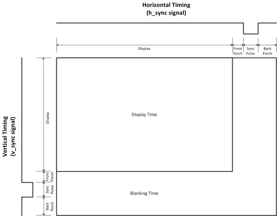
From what I understood, the basis of this protocol is always the same
(see slide 11 of NXP document)
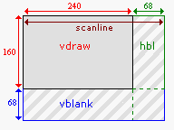
While it seems “easy”, the first problem is to identify
You can’t deduct the clocks for the resolution, because you have to handle the blanking time.
(see slide 12 of NXP document)
It means, for example, that the time defined by the line clock is not exactly the time to draw 240 pixels on a GBA screen. There is some blank included, perhaps to let the LCD actually draw the line? Same thing on vertical sync of course.
Developers use this blanking time a lot to compute data for next line or next screen, even more on system where CPU or data bus is no longer busy talking with LCD (faster!)
And these times are not publicly available :(
Source : https://www.coranac.com/tonc/text/video.htm
We know what we (may) have as input, let’s see what we need to have as output
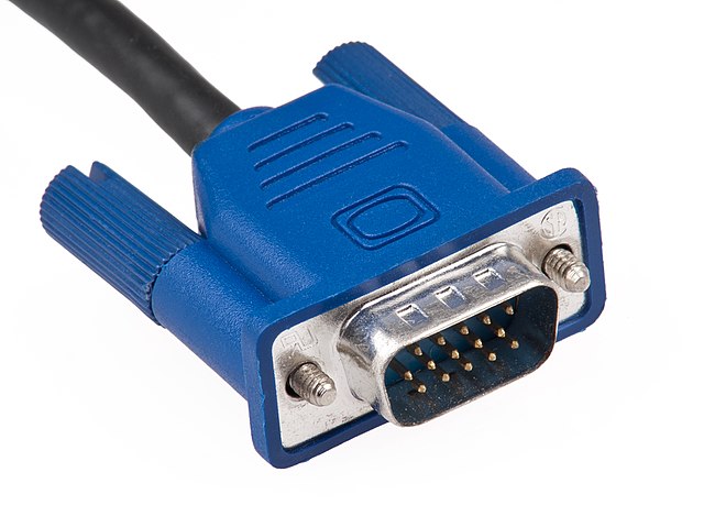
VGA is ...well...see Wikipedia, everything is explained there
https://en.wikipedia.org/wiki/Video_Graphics_Array
Yes, VGA is not only related to this connector
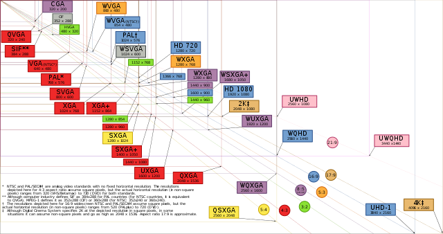
This connector allows a lot of resolutions, from 640x480 to ...very high definition:
Source : https://en.wikipedia.org/wiki/Display_resolution
And since color value flowing through it is an analog value, it can handle millions of them!
So VGA signal is defined by its dynamic resolution, dynamic colors count and dynamic frame rate.
Great so VGA accepts any kind of data, like the one of our LCD ?
Helas no. “Dynamic” here means you can select one of the available resolution/frame rate.
See http://tinyvga.com/vga-timing for some (if not all) of them.
Hopefully, the protocol is well known, and it’s why the connector is always the same
Pin | Signal | Description |
Pin 1 | RED | Red video (75 ohm, 0.7 V p-p) |
Pin 2 | GREEN | Green video (75 ohm, 0.7 V p-p) |
Pin 3 | BLUE | Blue video (75 ohm, 0.7 V p-p) |
Pin 4 | ID2/RES | Reserved since E-DDC, formerly monitor id. bit 2 |
Pin 5 | GND | Ground (HSync) |
Pin 6 | RED_RTN | Red return (Red Ground) |
Pin 7 | GREEN_RTN | Green return (Green Ground) |
Pin 8 | BLUE_RTN | Blue return (Blue Ground) |
Pin 9 | KEY/PWR | +5 V DC (powers EDID EEPROM chip on some monitors), formerly key |
Pin 10 | GND | Ground (VSync, DDC) |
Pin 11 | ID0/RES | Reserved since E-DDC, formerly monitor id. bit 0 |
Pin 12 | ID1/SDA | I²C data since DDC2, formerly monitor id. bit 1 |
Pin 13 | HSync | Horizontal sync |
Pin 14 | VSync | Vertical sync |
Pin 15 | ID3/SCL | I²C clock since DDC2, formerly monitor id. bit 3 |
Source : https://en.wikipedia.org/wiki/VGA_connector
So we have
You’ll notice there is absolutely nothing on resolution and color count…
Screen auto detect it from several things (mainly hsync/vsync)
If you want to know more, check https://www.epanorama.net/faq/vga2rgb/measuring.html
But it also means you have to be very VERY careful on the signals you use : one mistake and the screen thinks you’re using another resolution.
And unfortunately, it’s even more complex.
Not so far of what is done on LCD, VGA also uses several timings before/after hvsync:
on 640x480, HSync is not the time to draw 640 pixels and Vsync to draw 480 lines.
But, good news, these timings are fixed for each resolution, because, like explained below, screen detects the wanted resolution from this timing
Again, see http://tinyvga.com/vga-timing for more details.
While it seemed difficult at first, if you select a resolution, you’re no longer on a dynamic system but a fixed one.
The more difficult is in fact to select the right resolution which is
1/ available on most of the screen (yes, not all resolutions are supported by EVERY screen
2/ similar or almost similar to input resolution, see next chapter
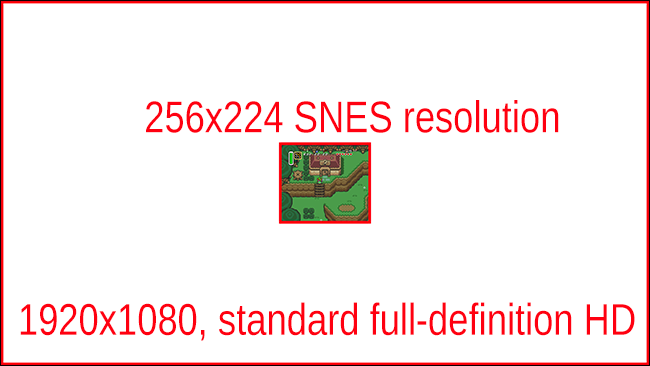
If we want to draw a LCD frame to a VGA screen, we can’t just rely on the original LCD resolution.
Imagine playing 160x144 GameBoy on a 1280x800 screen...even if it’s centered, I doubt you’ll be able to see anything….
source:https://www.howtogeek.com/341543/why-do-old-game-consoles-look-so-bad-on-modern-tvs/
If it’s not playable on a high resolution, we could try to use one of the smallest resolution available : the common 640x480 is the perfect choice.
Well, it will work but it will still be a thumbnail on a big screen, with black borders larger than the game screen itself.
The answer : you have to scale the LCD frame to fill the VGA screen, based on the native LCD resolution.
To scale the LCD frame, it means you have to draw a square and not a pixel/dot.
And be careful, not a rectangle, a square.
If you don’t use the same size for height and width of your scaled pixel, you’ll distort the frame...
The size of this square gives you the ratio (ex: a 4x4 pixel is a ratio of 4)
So you have to find the resolution which matches with the wanted ratio.
Let’s try with a ratio of 4 on the GameBoy Fat on a 640x480 resolution
640/4 = 160 -> great a ratio of 4 is perfect for the GameBoy Fat, with fill the width of the screen
480/4 = 120 -> 24 lines are missing
If height is the problem, start for there: you need at least 144x4 = 576
A valid VGA resolution of 576 height is 768x576
If you use this resolution, the video will be full height but you’ll need to center it at (768-160x4)/2 = 64
Another more common VGA resolution is 800x600, which set the 640x576:4 GameBoy screen to (80,12)
What about a ratio of 3 ?
160x3 = 480
144x3 = 432
Which means a resolution of 640x480, starting at (80, 24)
It’s not better or worse, you have to select the one you like the more.
Resolution | Ratio | Position | Notes |
640x480 | 4 | (0,0) | 24 lines missing at bottom |
640x480 | 3 | (80,24) | Odd ratio, incompatible with scan line |
768x576 | 4 | (64, 0) | Not so common resolution |
800x600 | 4 | (80,12) | Doesn’t fill screen Need more RAM |
VGA resolution will rarely be a perfect match of LCD resolution x ratio.
Define the ratio you want, select the resolution accordingly and compute the frame coordinate to start drawing the frame on screen. Nothing more.
(thanks to Furrtek for pointing me this issue which I totally missed)
Like explained before, LCDs have their own refresh rate.
It means they are refreshed/redrawn N times per seconds.
On the other side, VGA supports its own frame rates too : 50/60/75/….
Unless you are lucky and your system uses a standard frame rate, you’ll probably have to adapt refresh rate.
And, unfortunately, there is no ‘perfect’ solution to this problem.
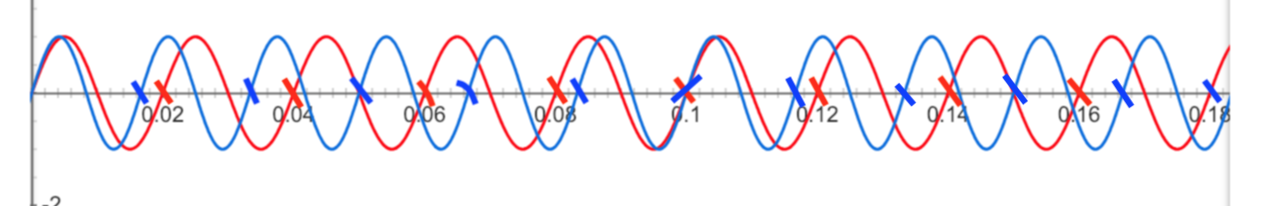
A picture is more efficient than a thousand words so
On Google search, tap “y=sin(60*x*2π ),y=sin(50*x*2π )” for a 60hz/50Hz comparison
On this graph, 2 values are plotted :
You could see VGA is refreshed BEFORE frame buffer is even full.
Congratulations, you know understand what is a video lag.
It’s small : buffer is filled at 0.02s and is flushed on screen at 0.033s
If you look what happen after some refresh, you’ll notice another problem
0,016 (empty) buffer is flushed to VGA
0,02 Buffer is filled
13ms
0,033 Buffer is flushed
0,04 Buffer is filled
9ms
0,049 Buffer is flushed
0,06 Buffer is filled
6ms
0,066 Buffer is flushed
0,08 Buffer is filled
2ms
0,082 Buffer is flushed
0,098 Buffer is flushed ⬅ !!
0,100 Buffer is filled
14ms
0,114 Buffer is flushed
0,120 Buffer is filled
10ms
0,130 Buffer is flushed
...
2 flush arised and delay between fill and flush high-to-low. It’s not technically a problem but it could be “felt” by the player when it happens too often.
Since VGA refresh rate is higher than system LCD refresh rate, obviously
1/ first VGA refresh occurs BEFORE LCD one
2/ VGA refresh may occur too fast between 2 LCD one
To avoid this, the 2 refresh rates must be as close as possible.
And you have to test it yourself, to feel if it’s a problem or not
To also have to know there is another way to minimize this :
Handle flush on the line level, not on the screen level.
But it requires a more complex design, perhaps even too much for the gain.
I won’t cover it on this document.
( not confident about what I wrote)
With Arduino-clones and other cheap CPU-based solutions available, you could think the choice is easy to make.
Did you notice at which rate you’ll need to decode the LCD frame and, in parallel, generate VGA signals ?
And higher is the resolution or bigger is the LCD frame, the more you’ll need to do to handle/generate a frame.
It’s clearly not doable with an Arduino.
A CPU executes instruction one by one.
A logic device reacts to signal and so everything that is linked to a signal is triggered ‘at the same time’.(⚠)
The only available solution is a CPLD/FPGA.
I’m still not sure to know the exact difference between the two apart from the limited capacity (speed, amount of memory it could handle,..) of the CPLD.
A CPLD is cheaper than a FPGA so if possible, prefer a CPLD like a very common Altera Max 2.
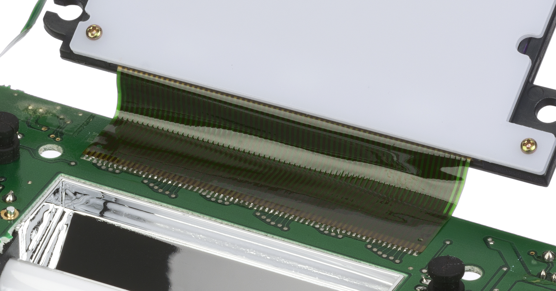
To decode a LCD frame, you should first identify how to get it.
Remember the basis of the protocol LCD screen use ?
You first need to find
1/ where are these signals (pinouts)
2/ what clocks values are used (and if they include blanking time and if they are fixed)
3/ any other data needed to fully decode a frame
This will give you the number of signals you have to handle, to select the right CPLD/FPGA
A perfect example is available here, for the GameBoy Fat : http://www.flashingleds.net/nintendOscope/nintendoscope.html
Craig explains how he did it (from get the pinout to decode a frame) and which mistakes to avoid
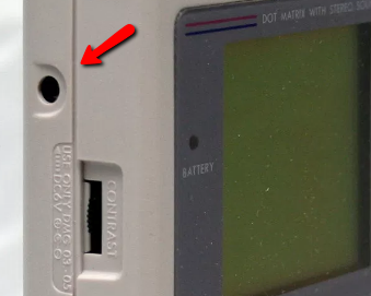
I really liked this one : “They're 5V logic levels, but watch out for the -30V DC contrast signal!”
So be sure to test every signal with a multimeter before attempting to sniff them!
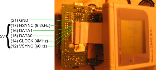
GameBoy FAT is probably the easier system to decode :
Every CLOCK, read DATA1/DATA0 to get the grey ID and increment X.
Every HSYNC, increment Y
Use VSYNC to reset X,Y
It’s a perfect system for a first try.
Of course, you need a buffer/memory.
Each system has its own BPP : Bits per pixel.
So
1 pixel = 1 byte for a 8BPP,
2 pixel = 1 byte for a 4BPP (if you want to optimize your buffer use, 1=1 else)
2 pixel = 3 bytes for 12 BPP (if you want to optimize your buffer use , 1 = 2 else)
If you target a <256colors system, for a standard buffer you need Height * Width * pixel weight
Ex: to store an unoptimized GameBoy frame, you need 160x144x1 = 23040bytes.
If you use bram (memory inside the FPGA), don’t forget it’s also used for your variables so don’t get it too short !
Of course, you could need more if you want to make some effects but it’s beyond this document.
Also, never forget you can’t write AND read at the same time
More details on https://electronics.stackexchange.com/a/269235
And unfortunately, since you could write and read a pixel (on a very extreme case, the SAME one) at the same time (see frameRate chapter), you have to handle this constraint.
I’m not totally sure about the real solution there.
Making some research and based on my own reflexion, I could list several possible answers
I personally prefer the double buffer way, even if it means you need twice the size of the buffer. (+ a few bytes needed for some vars). In 2021, it’s not a real problem, memory cost isn’t that much.
I could explain how to do it...but everything is already available here
http://www.cs.ucr.edu/~jtarango/cs122a_lab4.html
Perhaps less scholar there
https://www.digikey.com/eewiki/pages/viewpage.action?pageId=15925278
Another one I like a lot is Xess’s one, which I’ll probably base my design on
http://www.xess.com/blog/vga-the-rest-of-the-story/
Updated in http://www.xess.com/projects/an-103005-vgagen-project/
What you have to remember:
LCD color information is digital.
It could be id of color in system fixed pal or R, G and B values.
If color is coded on 9bit, it’s mostly 3bit for R, 3bit for G, 3bit for B.
(be careful, sometimes B uses less bits than others, because human eyes is less sensitive to blue)
VGA color is analog.
Signal levels are between 0 (completely dark) and 0.7 V (maximum brightness) control the intensity of each color component (R,G,B), which combine to make the final color of a pixel on the monitor screen.
So you have to find a way to convert a Red value from 0 to 0x7 (if 3bit) to 0 to 0.7v :
A digital-to-analog converter or simply DAC.
https://www.digikey.com/en/articles/techzone/2017/sep/adc-dac-tutorial
Never forget 0.7v is required on “monitor side”, so if your DAC doesn’t output 0.7v at max, you have to add a resistor to create a voltage divider circuit.
The most useful page about this subject is https://chipnetics.com/tutorials/understanding-75-ohm-video-signals/
From what I read, impedance of the circuit should also be 75 ohm but impedance is my worst nightmare : I don’t understand a thing about it :(
So nothing on this subject for now, sorry
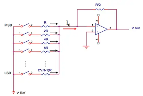
To convert a digital to analog value, you could use one of these DAC:
https://www.youtube.com/watch?v=PoOm_G4s1dE
http://www.pyroelectro.com/tutorials/fpga_vga_resistor_dac/theory.html
(based on from https://electronics.stackexchange.com/a/453444)
0.7v = max value on full brightness (or anything higher value if you use a voltage divider)
Input = 5V/3.3V/….
75ohm = impedance
Rx = parallel combination of the N resistances
Ry = voltage divider
0.7V = input * Ry/(Rx+Ry)
or Ry = Rx/((input/0.7)-1)
Rx | Ry = 75ohm/2
or Ry = 37.5*Rx/(Rx-37.5)
=> Rx = 37.5+(input/0.7)-1)*37.5
=> Ry = 1/(1/Rx+1/75-1/37.5)
1/Rx = 1/(R1*1)+1/(R1*2)+1/(R1*4)+...+1/(R1*2^x)
=> R1 = Rx+(Rx/2)+(Rx/4)+....+(Rx/2^x)
=> R2 = 2*R1
=> R3 = 4*R1
=> Rn = 2^(n-1)*R1
Cons :
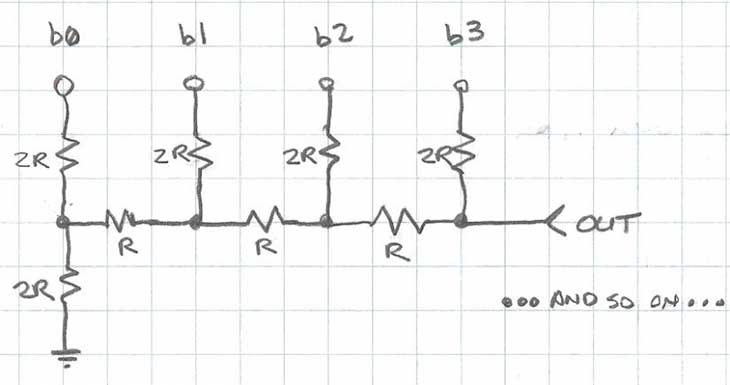
https://www.youtube.com/watch?v=Pc1aFloxSMw
https://fr.tek.com/blog/tutorial-digital-analog-conversion-r-2r-dac
If you have a box of N resistors at 1% tolerance, whatever is the value : go for it !
Based on https://create.arduino.cc/projecthub/instrumentation-system/dac-8-bit-using-r-2r-ladder-964837
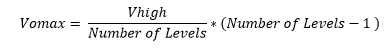
With Vomax, you can then compute the value of the resistor needed for your voltage divider
With Vin = Vomax, Vout = 0.7v, R1 = your resistor R …. So R2 is the resistor value to add in parallel of monitor 75ohm terminator
another formula I’m not sure about…
Pros :
need 2 values of resistor only (down to 1 if you use them is serial)
Cons :
1% resistors to ensure the ladder works correctly.
12 to 13 bits maximum (see http://www.freepatentsonline.com/7362253.html)
A video DAC is very powerful.
If you browse Analog’s one, you’ll find cheap to expensive ICs
https://www.analog.com/en/parametricsearch/11355
The difference of price is defined by
So you have to select what you really want to output to be able to select the right IC.
But be careful with your BOM list ! And note that your PCB design will be more complex.
Cons :
Price
complex IC needs some ticks to process data, resulting in some delays
See http://www.eecg.toronto.edu/~tm4/rgbout.html
Pros :
Could be useful for some others of part of your circuit
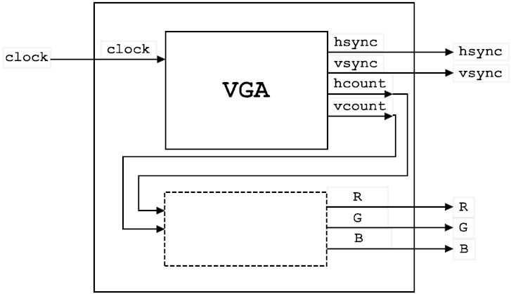
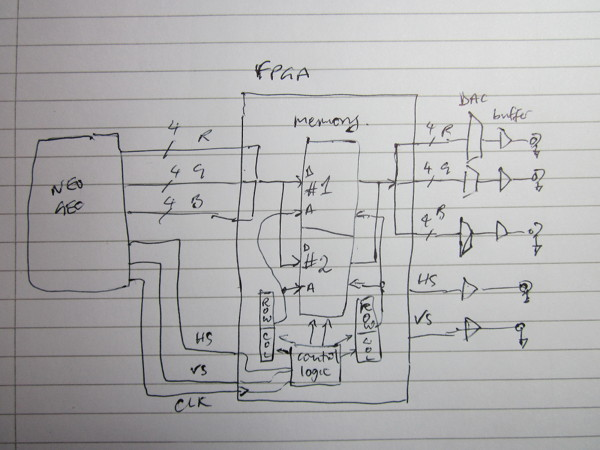
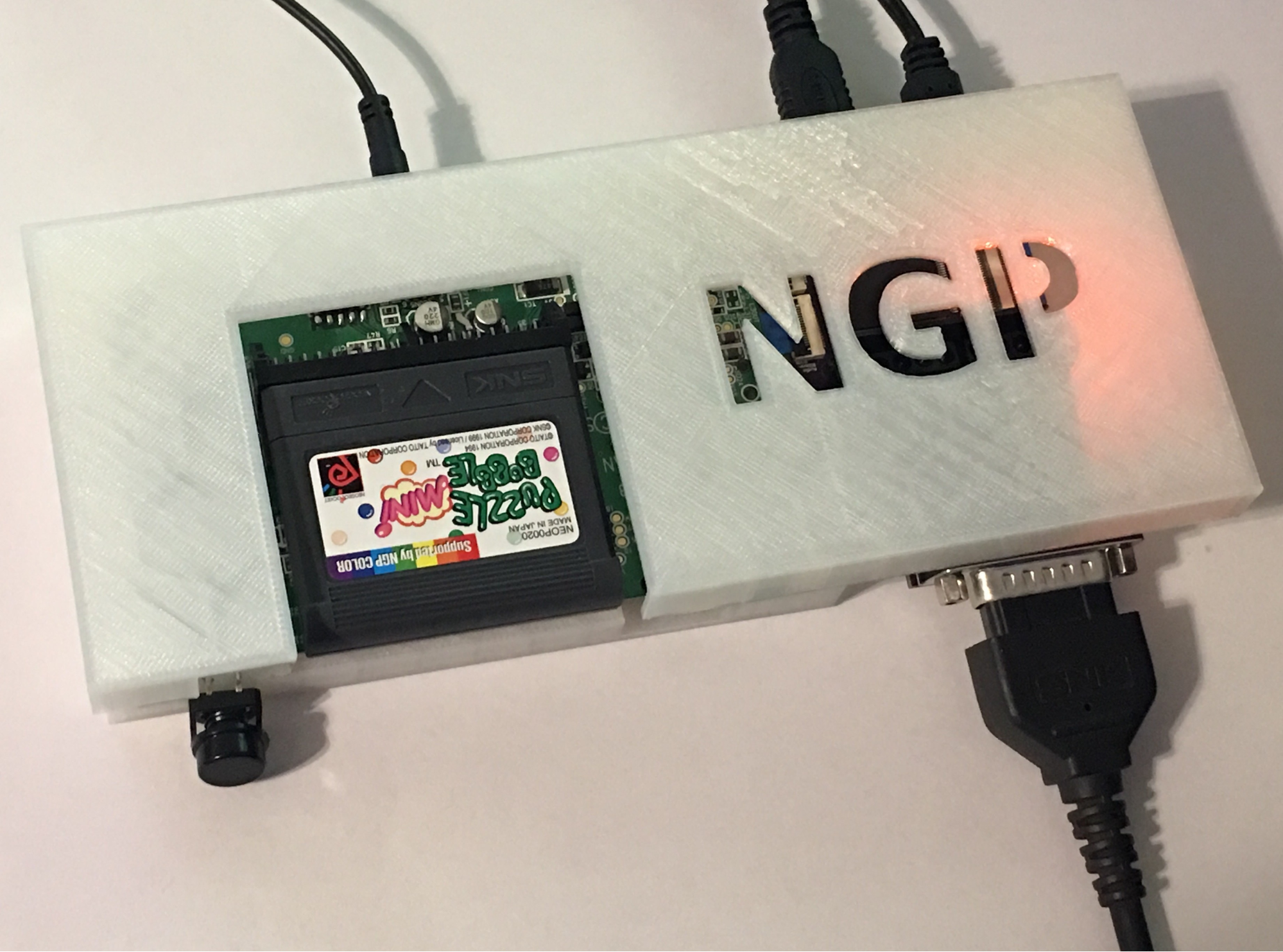
Based on the previous data, we could design a xx2vga adapter :
LCD signal defines a LCD frame, pixel per pixel, based on the clock signals.
We store this pixel data in a buffer, at the right entry.
When the buffer is full, the buffer is swapped and the LCD frame restarts at (0,0).
The full buffer is used to generate the right RGB values, based on VGA clock signals and using a R-2R ladder DAC.
We could be done in pseudo code
On Start
LCD_idx = 0
VGA_idx = 0
Active_buffer = 0
Buffer = [2][buffer_size]
On LCDPixelClock
Buffer[active_buffer][LCD_idx] = LCD_pixel
LCD_idx++
On LCDVSync
Active_buffer = (active_buffer+1)%2
LCD_idx = 0
On VGAClock
(handle timing)
VGA_RGB = buffer[active_buffer^1][VGA_idx]
VGA_idx++
On VGAVSync
VGA_idx = 0
⚠ I didn’t use HSync clocks...it seems I didn”t really need it but perhaps I should to prevent error
active_buffer is set by LCD core, so based on refresh rate issues, we could start to draw from a buffer and finish from another...no way to handle it ?!
While it goes beyond the goal of this document, I also listed some informations related to the “consolization” of portable system
Video
Power
Input :
Enclosure
If you want to give a retro style to video, you can’t bypass scanline generator
Scanline generator adds a dark line every X lines (2 is the more common option)
TODO : dark = black / not draw / dark gray? See GBA Consolize options
Very easy to add : just draw the same value on even (or odd line).
More efficient with an even ratio.
Source : http://www.smallcab.net/generateur-scanline-slg3000-p-307.html
I recently discovered the gridlines.
While the scanlines mimics the CRT output, gridlines mimics LCD structures.
So if you want a BIG LCD screen, use gridlines.
-> Add horizontal dark line every X row.
Keep original aspect ratio or fill screen.
This document uses a fixed aspect ratio but you can also use a ratio different for height and width to fill the screen.
TODO
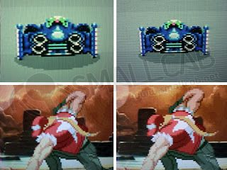
Some LCD keeps a ‘blurred’ previous frame, which means you should not clear screen before flushing a frame but do some XOR.
Some games even use it to trick and be able to simulate more colors (palette change each frame) or to improve the movement effect (like on shmup of bullets look to have a tail)
TODO
Whatever option you choose, you have to be very careful on signal level between system and mod.
If system and mod don’t use same signal power (like the infamous 5V vs 3.3V), you’ll need to use some level xxx like the TXB by Texas Instrument on each signal, and share the ground.
You also need to answer these questions :
What power (volt/current) deliver the system ? TODO
What current it REALLY need ? TODO
What power (volt/current) need the mod ? TODO
TODO
See introduction
TODO (raw comment without electronic confirmation, to heavily challenge!)
Based on system and mod needs, you’ll be able to select the unique power input needed
If system and mod don’t use the same voltage, you’ll need to keep in mind the power lost on voltage transform.
So
V : max(system V, mod V)
A : system’s current + mod’s current + current lost on volt transformation
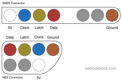
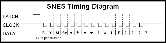
While the connector is different, the protocol is the same for these 3 systems
NES Controller Port | SNES Controller Port | Famicom Controller Port |
Pinout Data | |||
Pin Name | NES Pin # | SNES Pin # | Famicom Pin # |
GND | 1 | 1 | 8 |
P/S (Latch) | 3 | 5 | 12 |
Clock | 7 | 6 | 10 |
Data | 5 | 4 | 11 |
Vcc +5v | 2 | 7 | 9 |
Data 2 | 4 | N/A | N/A |
Data 3 | 6 | N/A | N/A |
Data 2 and Data 3 are not used for normal controllers.
For the NES they're used for things like the Zapper and other specialized controls (Arkanoid paddle, etc).
For the SNES - these lines are reserved for use with things like the Super Scope.
Source : https://gamesx.com/wiki/doku.php?id=controls:nes_snes_controller
If your lost, here is visually what it means :
5V, timing based (6µs)
http://www.fpgalover.com/ip-cores/snes-controller-core
(only support joypad, no special controller using data2/data3)
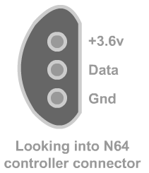
1 wire data! Data protocol is (very) time sensitive : 1µs
http://www.fpgalover.com/ip-cores/n64-controller-module
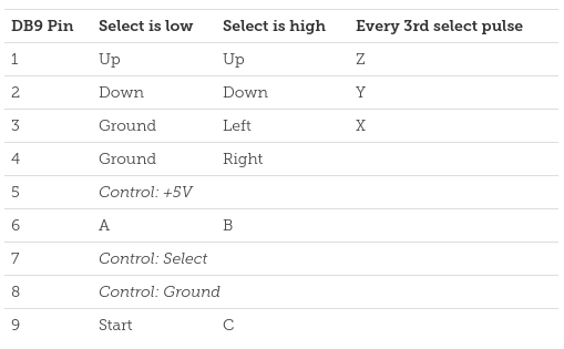
SMS controller use a DB9 connector so it’s easy to get one
https://www.raspberryfield.life/2018/11/11/sega-master-system-controller/
Not really needed, you read data
MD controller use a DB9 connector so it’s easy to get one
https://www.raspberryfield.life/2019/02/15/sega-mega-drive-genesis-3-button-abc-controller/
https://www.raspberryfield.life/2019/03/25/sega-mega-drive-genesis-6-button-xyz-controller/
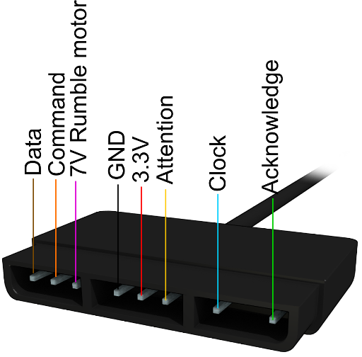
No FPGA core available (?), but since it uses SPI protocol, it should be doable
https://gamesx.com/controldata/psxcont/psxcont.htm
https://store.curiousinventor.com/guides/PS2
If you use bluetooth pad, you’ll need a bluetooth receiver of mod side
TODO : FPGA cores
TODO : Bluetooth receiver IC
TODO : pairing
TODO : power
If you transform your system as input bluetooth controller, you’ll need a bluetooth receiver of mod side and a custom emitter on system side, probably on a custom PCB or hacking system PCB
See Bluetooth pad for receiver and pairing details
TODO : FPGA cores
TODO : Bluetooth emetter IC
TODO : power
TODO : no RF pad, like bluetooth ?
TODO : RF emitter / receiver
TODO : pairing
TODO : power
I don’t know a thing about debugging FPGA.
My approach for now is to
TODO
Here is a list of the errors I met and how I fixed them, perhaps it will help you…
COMING SOON…(perhaps)
Resolution | 160x144 | |
Colors | 4 colors - 2 bits | |
Buffer size | 23040 bytes | Using one byte per pixel It’s possible to use less story 4 pixels per byte |
Saleae dump | Dump : Screen : Igor pro script : | From game XXXX |
Power | LCD data are 5V logic level | GameBoy is 6V 0.7W via 4xAA batteries or AC Adapter |
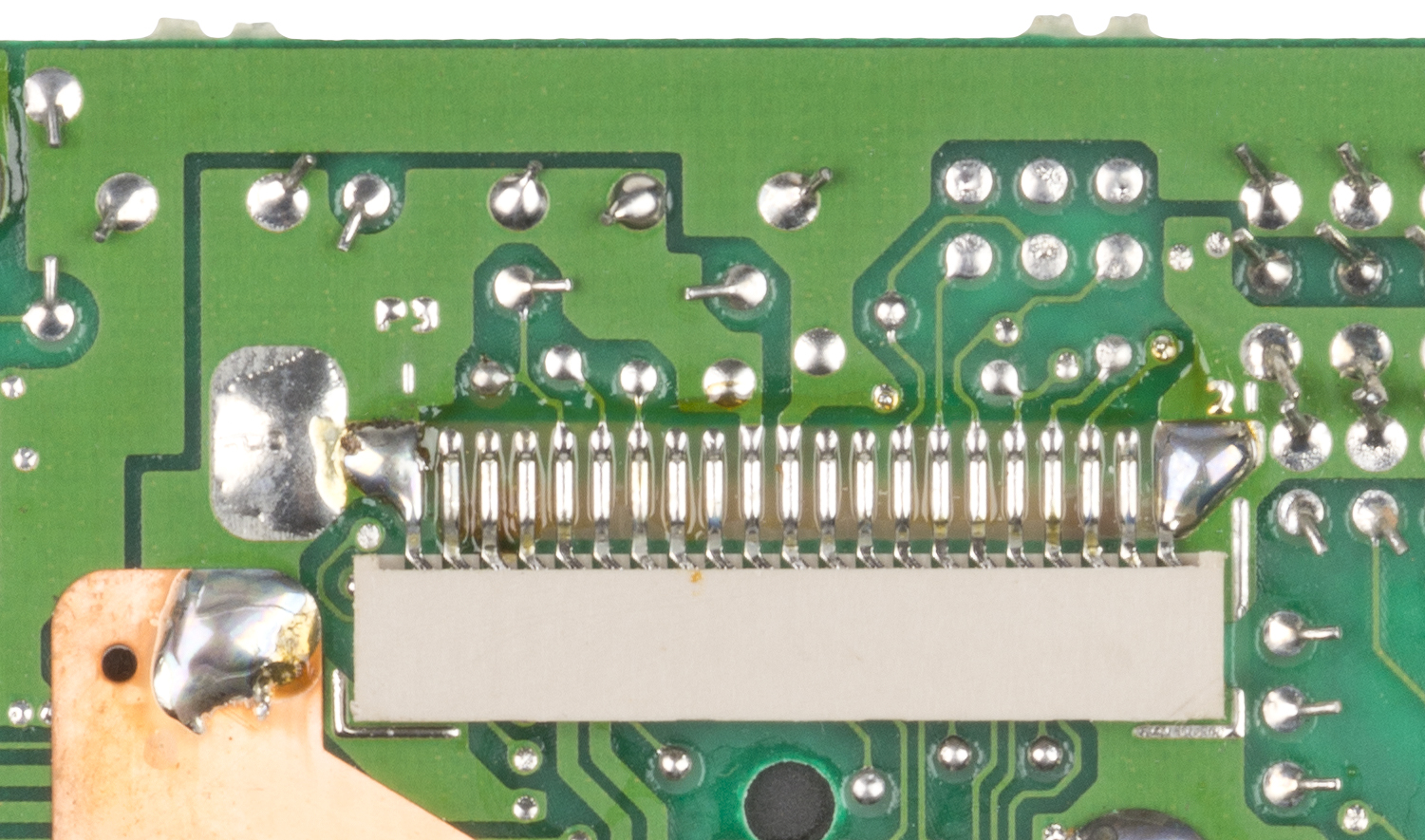
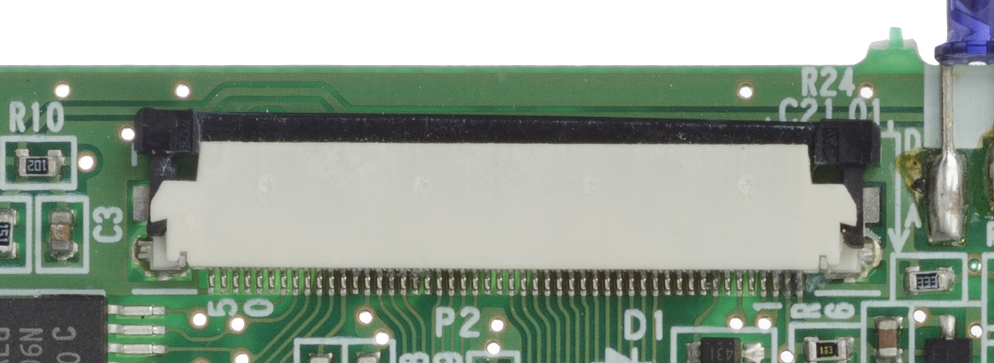
Pinout | 21: GND 17: HSync 16: DATA1 15: DATA0 14: Pixel clock 12: VSync | Cable used is a FDC ribbon cable awm 20624 80c 60v vw-1 21pin - pitch xxx mm |
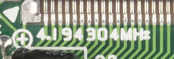
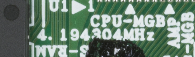
Pixel clock | 4.194304MHz | |
HSync | 9.2KHz | |
VSync | 60Hz | Probably 59.7Hz |
On each pixel clock rising edge, pixel value is inserted via DATA0 and DATA1
HSync isn’t needed since pixel clock stops while in blanking period.
VSync isn’t needed but it’s a good point to use it to reset current pixel counter...and you could use it as rate for VGA if you want.
Ratio : 4
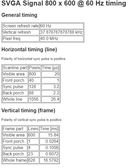
Resolution : 800x600@60Hz
Timings : http://tinyvga.com/vga-timing/800x600@60Hz
Coordinate : (80,12)
TODO : details
TODO : board
TODO : code
Link : https://bennvenn.myshopify.com/products/porchie-the-vga-out-board-for-your-dmg?variant=20483149319
Source : n/a
Price : 37$
Resolution : 640x480 / ratio 2 (!)
FPGA : Altera
Connection : soldering
Remark :
Link : https://store.kitsch-bent.com/product/easy_vga
Source : https://github.com/uXeBoy/VGA1306
Price : 38$
Resolution : 640x480 / ratio 2
Connection : soldering
FPGA : iCE40HX1K-EVB (?)
Remark :
https://www.gamebox.systems/products/dmtv-pcb-gameboy-vga-controller-replacement-board
Source : n/a
Price : 67$
Connection : cable
Remark :
Link : http://longhornengineer.com/category/projects/hardware/gameboy-dmg-01-vga/
Source : https://github.com/LonghornEngineer/DE0_GameBoy_DMG-01_VGA
Price : n/a
Resolution : 1280x1024@60Hz / ratio ?
Connection : ?
FPGA : DE0 Digital IO Wing
Remark :
Link : https://kiedontaa.blogspot.com/2019/12/gameboy-to-vga.html
Source : https://github.com/ahhuhtal/gbvga
Price : n/a
Resolution : 800x600 @ 60 Hz / ratio 4
Connection : ?
FPGA : Cyclone 1
Remark :
Link : https://ackspace.nl/wiki/Gameboy_VGA_adapter
Source : n/a
Price : n/a
Resolution : 768x576@59,7Hz
Connection : ?
FPGA : Altera Cyclone 2
Remark :
Link : http://djtransformer.com/shop/product.php?id_product=50
Source : n/a
Price : 100L / too much
Resolution : ?
Connection : ?
FPGA : ?
Remark :
Link : https://snesy.wordpress.com/2011/02/12/gameboy-vga/
Source : n/a
Price : n/a
Resolution : ?
Connection : ?
FPGA : ?
Remark :
Link : http://www.hdmyboy.com/play/
Source : n/a
Price : ?
Resolution : 1120x1007 or 1920x1007
Connection : cable, in sandwich between back and front
FPGA : ?
Remark :
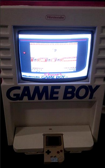
https://www.retrorgb.com/supergameboy.html
https://www.retrorgb.com/gameboyinterface.html
Some GBA projects also handle GB/GBC, see below
http://www.chrismcovell.com/demovision.html
http://www.chrismcovell.com/wideboy.html
https://twitter.com/kelslewin/status/963569660254924800
https://www.reddit.com/r/Gameboy/comments/bo9e0l/saw_this_awesome_mod_on_instagram_and_was/
Seems to use Porchie
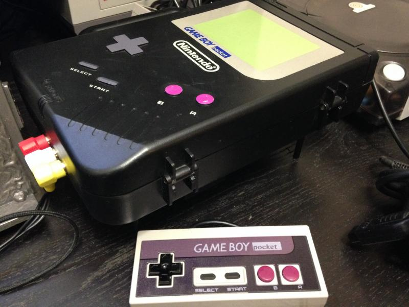
https://atariage.com/forums/topic/276525-consolized-dmg-orig-gameboy/
http://france.retrogaming.fr/tutoriaux/fabrication-borne-demonstration-game-boy/
Similar to GameBoy FAT.
Resolution | 160x144 | |
Colors | 4 colors - 2 bits | |
Buffer size | 23040 bytes | Using one byte per pixel It’s possible to use less story 4 pixels per byte |
Saleae dump | See GameBoy FAT | |
Power | LCD data are 5V logic level | Pocket: 3 AAA 3V, 2.35mm x 0.75mm DC jack Light: 2 AA 3V, xxxxx |
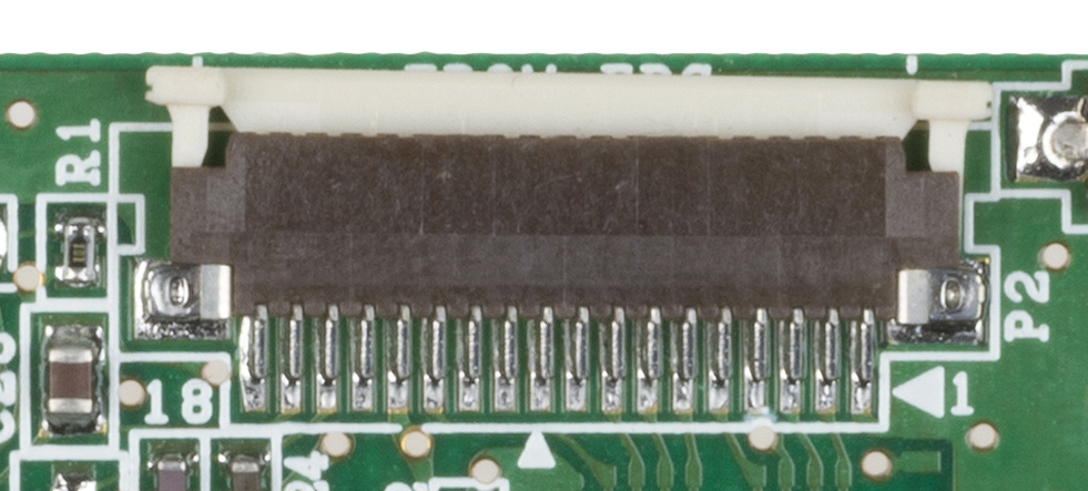
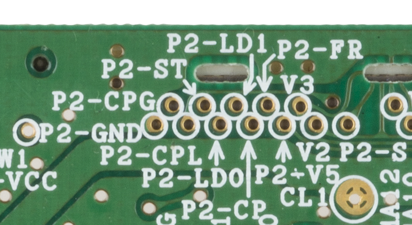
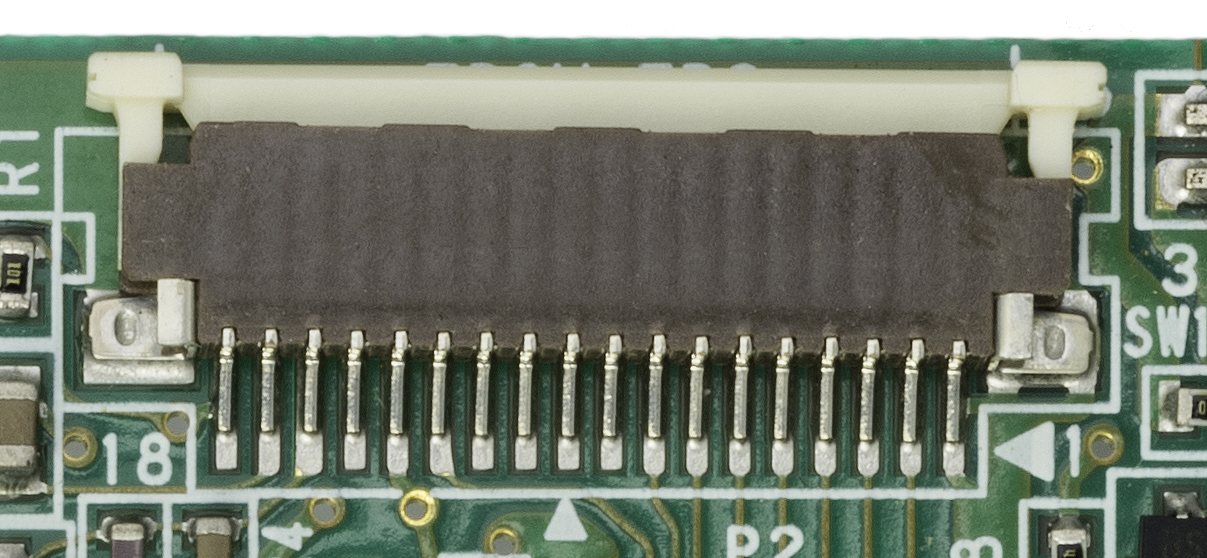
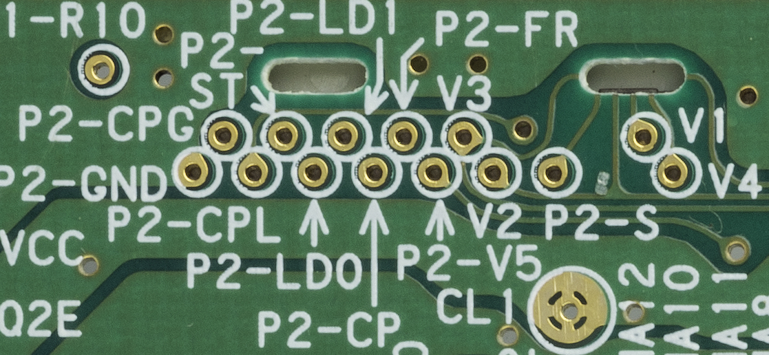
Pinout pocket | 4: HSync 5: DATA0 6: DATA1 7: Pixel clock 13: VSync | Cable used is … P2-LD0 : DATA0 P2-LD1 : DATA1 P2-ST : HSync P2-S : VSync P2-CP : Clock P2-CPG : LCD enable |
Pinout light | ||
Pixel clock | 4.194304MHz | |
HSync | 9.259kHz | |
VSync | 59.7275Hz | Not exactly 60Hz |
More details on each PIN at http://forum.gameboyre.com/thread/209-%E6%8A%9B%E7%A0%96%E5%BC%95%E7%8E%89-gbp%E6%94%B9%E8%83%8C%E5%85%89%EF%BC%8C%E7%9B%B4%E6%8E%A5%E6%8D%A2%E5%B1%8F%EF%BC%8C%E7%AD%89%E4%B8%93%E5%AE%B6%E9%A3%9E%E7%BA%BF/
Similar to GameBoy FAT
Similar to GameBoy Fat
TODO : LCD pinout converter board if needed (light, pocket, fat in one)
Link : https://web.archive.org/web/20110217020511/http://www.rival-corp.com/2010/12/02/gameboy-vga-adapter-2/
Source : n/a
Price : n/a
Resolution : ?
Connection : ?
FPGA : Altera Cyclone II
Remark : https://www.youtube.com/watch?v=NUIWsUHntf8&feature=emb_logo
Link : https://www.youtube.com/watch?v=wUWLFWUJgus-Pocked-VGA-video-output
Source : https://github.com/zlakomanoff/gameboy-vga-vhdl
Price : ?
Resolution : 768 x 576 @ 60 Hz
Connection : ?
FPGA : Cyclone 2
Remark :
Same as GameBoy FAT
TODO
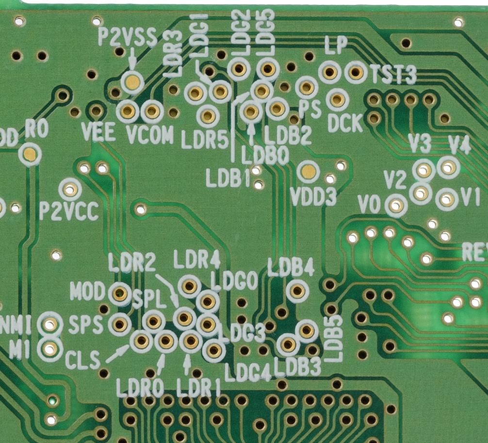
Resolution | 160×144 | |
Colors | 32768 - 15bit (5 per channel) | But only up to 56 at the same time on screen |
Buffer size | 76800 | 2bytes per pixel |
Saleae dump | Dump : Screen : Igor pro script : | |
Power | 3V 2AA | |
Pinout | See test point: LDR0-4 : red LDG0-4 : green LDB0-4 : blue SPL : HSync SPS : VSync DCK : pixel clock | |
Pixel clock | ||
HSync | ||
VSync |
TODO
Ratio : ?
Resolution : ?x?@?Hz
Timings : http://tinyvga.com/vga-timing/?x?@?Hz
Coordinate : (?,?)
TODO
Link : https://web.archive.org/web/20101218141357/http://www.rival-corp.com/2010/12/07/
Source : n/a
Price : n/a
Resolution : n/a
FPGA : Cyclone 2 (Altera DE1 board)
Connection : n/a
Remark :
Link : https://www.retrorgb.com/mcwill-backlit-gbc-screen-kit.html
Source : n/a
Price : 75$
Resolution : 640×480 @ 60Hz
FPGA : n/a
Connection : 2 solder points and cable
Remark :
Link : https://blog.gameboymania.com/2014/03/for-old-games.html
https://www.retrorgb.com/gameboyinterface.html
Some GBA projects also handle GB/GBC (see below)
TODO
Resolution | 240x160 | |
Colors | 32768 - 15bit (5 per channel) | |
Buffer size | 76800 | 2bytes per pixel |
Saleae dump | Dump : Screen : Igor pro script : | |
Power | GBA: 3V (2xAA) GBA SP: Battery Li Ion | |
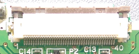
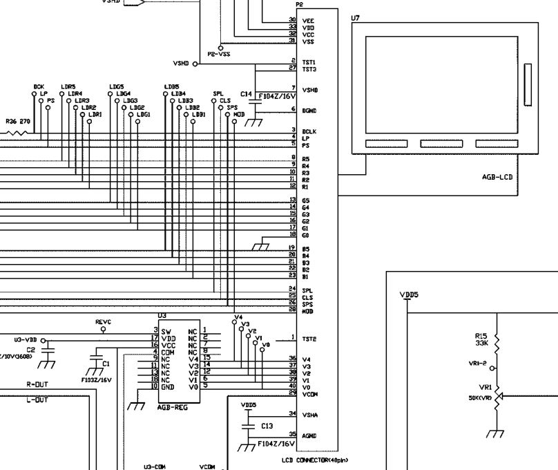
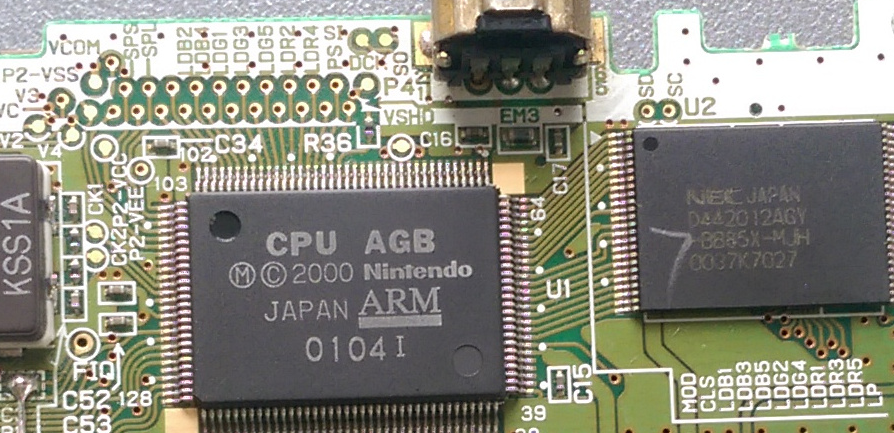
Pinout | http://problemkaputt.de/gbatek.htm#pinoutslcdcables | |
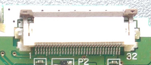
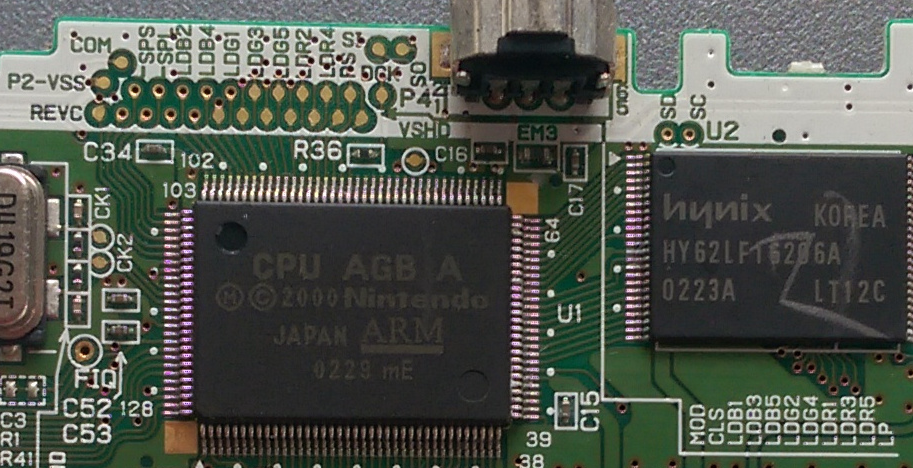
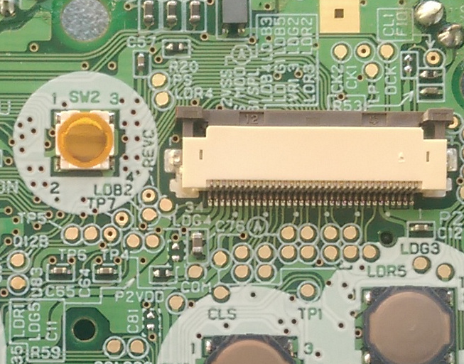
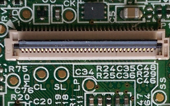
GBA 40 | 40 pin connector 3 : Pixel Clock 8-12 : Red 1-5 13-17 : Green 1-5 19-23 : Blue 1-5 24 : HSync 26 : VSync | Test points: DCK : Pixel Clock SPL : HSync SPS : VSync LDR1-5 : Red LDG1-5 : Green LDB1-5 : Blue |
GBA 32 | ? : Pixel Clock ?-? : Red 1-5 ?-? : Green 1-5 ?-? : Blue 1-5 ? : HSync ? : VSync | Test points (see GBA 40) |
GBA SP | 34 pin connector 2 : Pixel Clock 7-11 : Red 1-5 12-16 : Green 1-5 18-22 : Blue 1-5 23 : HSync 25 : VSync | Test points DCK : Pixel Clock SPL : HSync SPS : VSync LDR1-5 : Red LDG1-5 : Green LDB1-5 : Blue |
GBA Micro | 34 pin connector 13 : Pixel Clock ? 4-8 : Red 1-5 ? 15-19 : Green 1-5 ? 21-25 : Blue 1-5 ? 12 : HSync ? 27 : VSync ?
| Test points: TODO |
Pixel clock | 16.78MHz | ? |
HSync | 16.620KHz | |
VSync | 59.737Hz | |
http://problemkaputt.de/gbatek.htm#lcddimensionsandtimings
https://www.insidegadgets.com/2019/08/08/playing-around-with-the-gba-lcd/
Ratio : ?
Resolution : ?x?@?Hz
Timings : http://tinyvga.com/vga-timing/?x?@?Hz
Coordinate : (?,?)
TODO
Link : https://shop.insidegadgets.com/product/advancevga/
Source : n/a
Price : 65$
Resolution : 800×600@59.73Hz
FPGA : Altera Max10
Connection : solder and cable
Remark :
Link : https://www.game-tech.us/product/gba-consolizer/
Source : 150$
Price : n/a
Resolution : 1280×720
FPGA : Xilinx ? (since use .MCS firmware)
Connection : n/a
Remark :
Link : https://www.facebook.com/BennVennElectronics/videos/1285539328226184/
Source : ??$
Price : n/a
Resolution : 640x480@59Hz
FPGA : Altera Max2
Connection : ?
Remark :
http://www.konlabs.com/articles_data/gba_transverter/index.htm
https://www.retrorgb.com/gbatv.html
https://www.retrorgb.com/gbacompare.html
http://www.sega-16.com/forum/showthread.php?24995-Let-s-consolize-a-GameBoy-Advance
Resolution | 224x144 | Portrait / Landscape mode |
Colors | 8 or 16 shades of grey - 4bit | |
Buffer size | 32256 | 1byte per pixel /2 if 2pixel per byte |
Saleae dump | Dump : Screen : Igor pro script : | |
Power | 1 AA | |
Pinout | ? : Pixel Clock ? : Grey 0 ? : Grey 1 ? : Grey 2 ? : Grey 3 ? : HSync ? : VSync | |
Pixel clock | 3.072MHz | |
HSync | 12KHz | |
VSync | 75.47Hz |
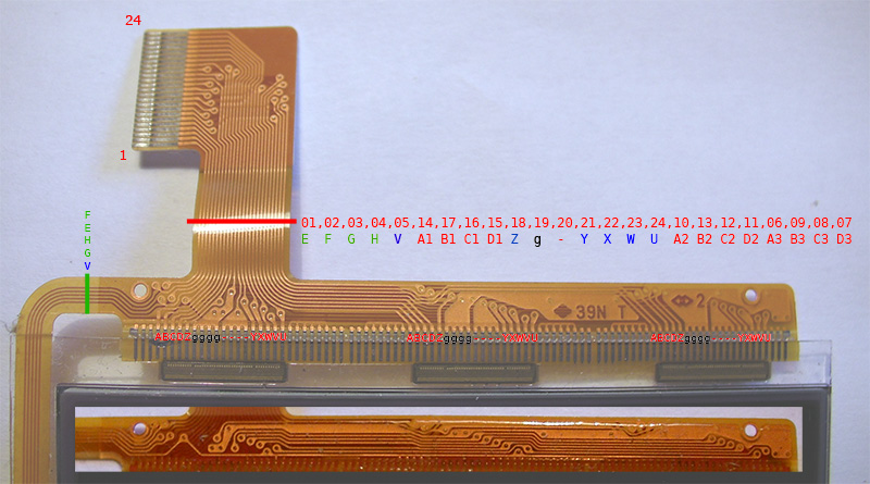
http://daifukkat.su/docs/wsman/#hw_dispcon
TODO
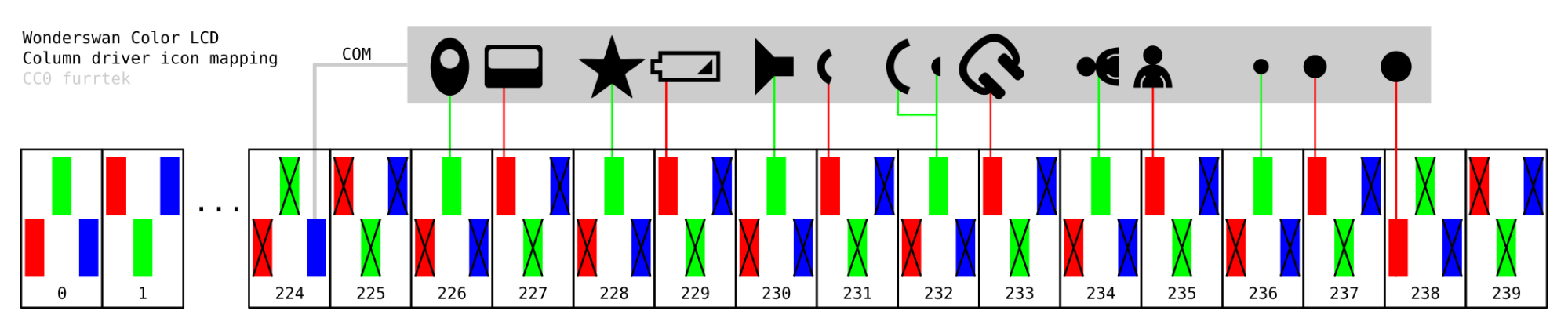
LCD icons send on LCD Signal
Portrait / Landscape mode
Ratio : ?
Resolution : ?x?@?Hz
Timings : http://tinyvga.com/vga-timing/?x?@?Hz
Coordinate : (?,?)
TODO
None on Classic (see Color is back compatible with Classic game)
None on Classic
None
Resolution | 224x144 | Portrait / Landscape mode |
Colors | 4096 (12 bit) | WS Mode available |
Buffer size | 64512 | 2 bytes per pixel |
Saleae dump | Dump : Screen : Igor pro script : | |
Power | 1 AA | |
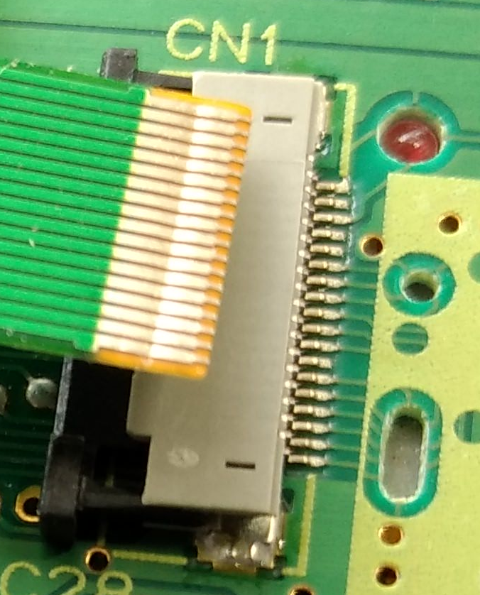
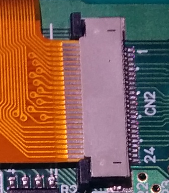
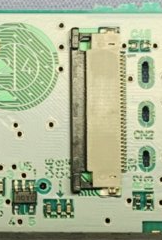
Pinout | TODO : same value on RGB on WS mode ? | |
WSC | 24 pin connector ? : Red 0 ? : Red 1 ? : Red 2 ? : Red 3 ? : Green 0 ? : Green 1 ? : Green 2 ? : Green 3 ? : Blue 0 ? : Blue 1 ? : Blue 2 ? : Blue 3 ? : Pixel Clock ? : HSync ? : VSync | No test points |
Crystal | 30 pin connector ? : Red 0 ? : Red 1 ? : Red 2 ? : Red 3 ? : Green 0 ? : Green 1 ? : Green 2 ? : Green 3 ? : Blue 0 ? : Blue 1 ? : Blue 2 ? : Blue 3 ? : Pixel Clock ? : HSync ? : VSync | No test points |
Pixel clock | 3.072MHz | |
HSync | 12KHz | |
VSync | 75.47Hz |
TODO
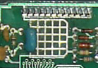
(you could see the 3 vertical ‘drivers’ on this pice from Furrtek on Yaronet post)
https://twitter.com/furrtek/status/1191770777802215425
To enable icons, pixel #224 blue level must be 0. To show the battery icon for ex., pixel #229 red level must be max.
Ratio : ?
Resolution : ?x?@?Hz
Timings : http://tinyvga.com/vga-timing/?x?@?Hz
Coordinate : (?,?)
TODO
Link : https://web.archive.org/web/20150516141817/http://www.yaronet.com/posts.php?s=167922
Source : n/a
Price : n/a
Resolution : n/a (ration H != ratio V)
FPGA : n/a
Connection : n/a
Remark :
Link : https://blog.gameboymania.com/2014/03/for-old-games.html
Source :
Price : n/a
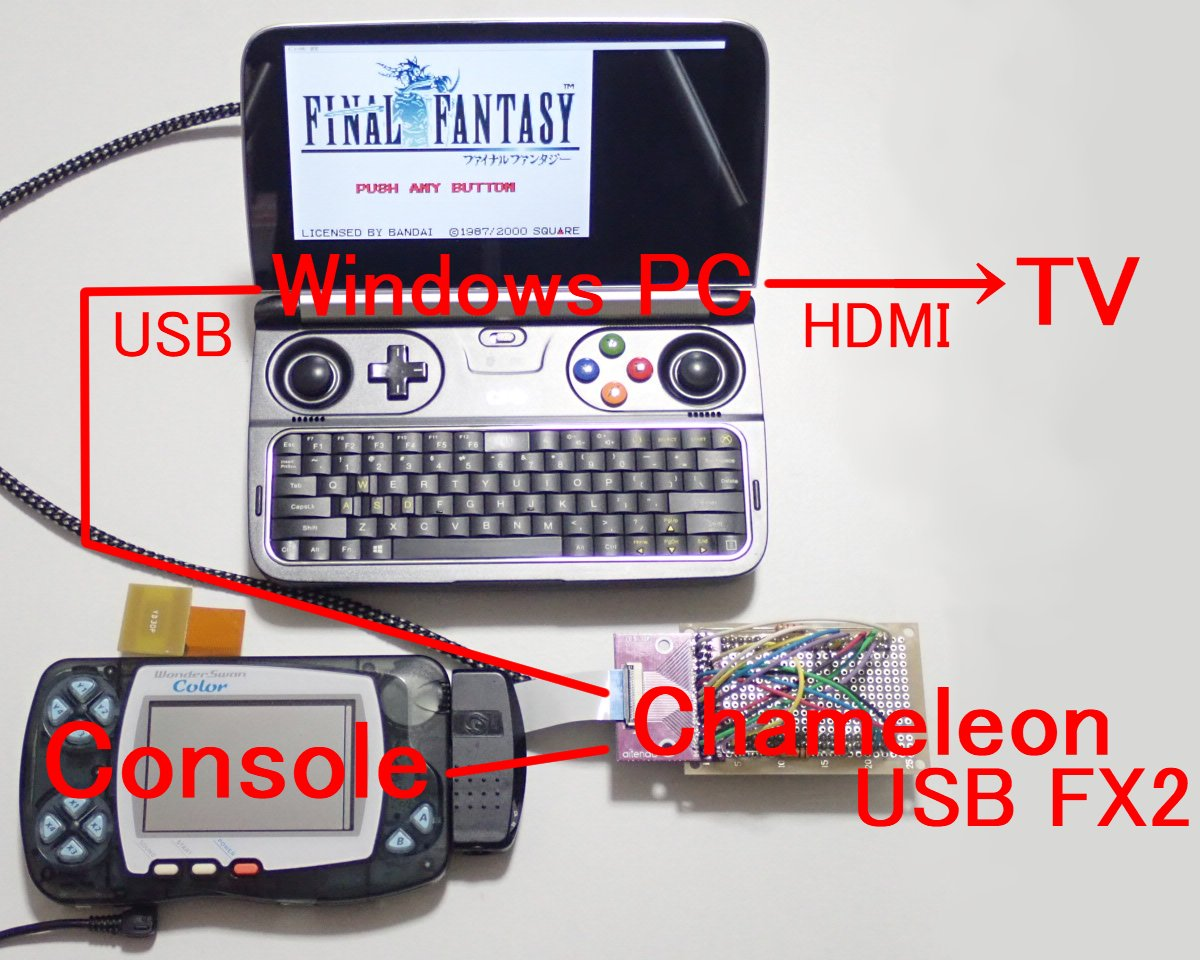
Resolution : 1120x720@ratio 5
FGPA : Cypress EZ-USB F2LP + Altera Max 2
Connection : n/a
Remark:
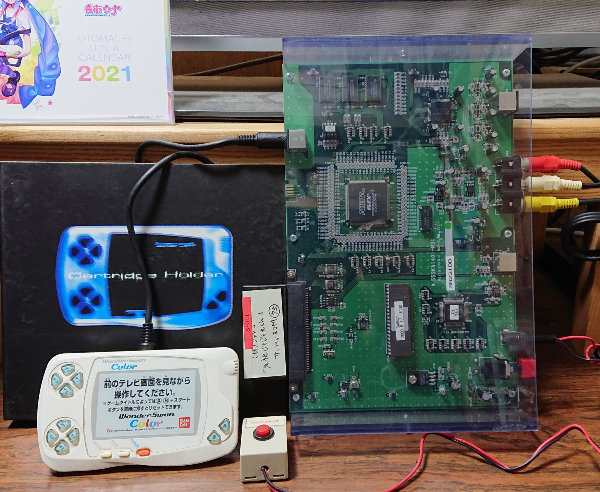
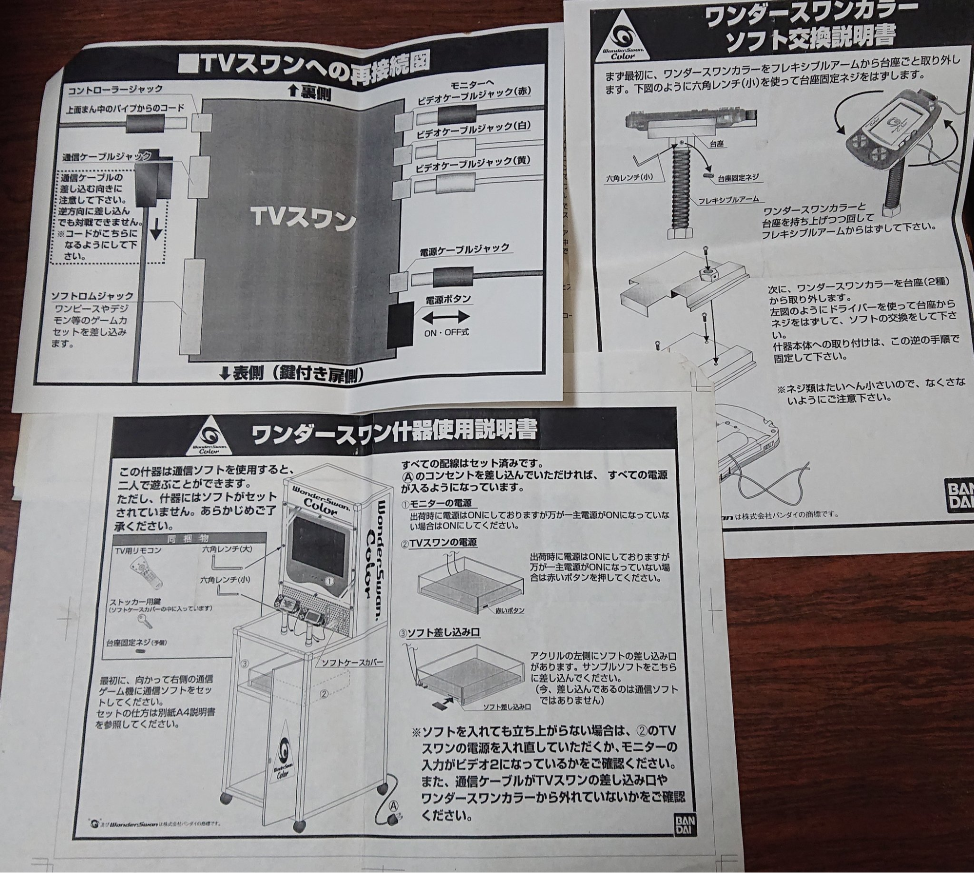
TVSwan (officiel, used in kiosk)
Need a swan to send video signals and a swan for input (?)
https://twitter.com/ts76573/status/1337285719488745472
Support Makaimura
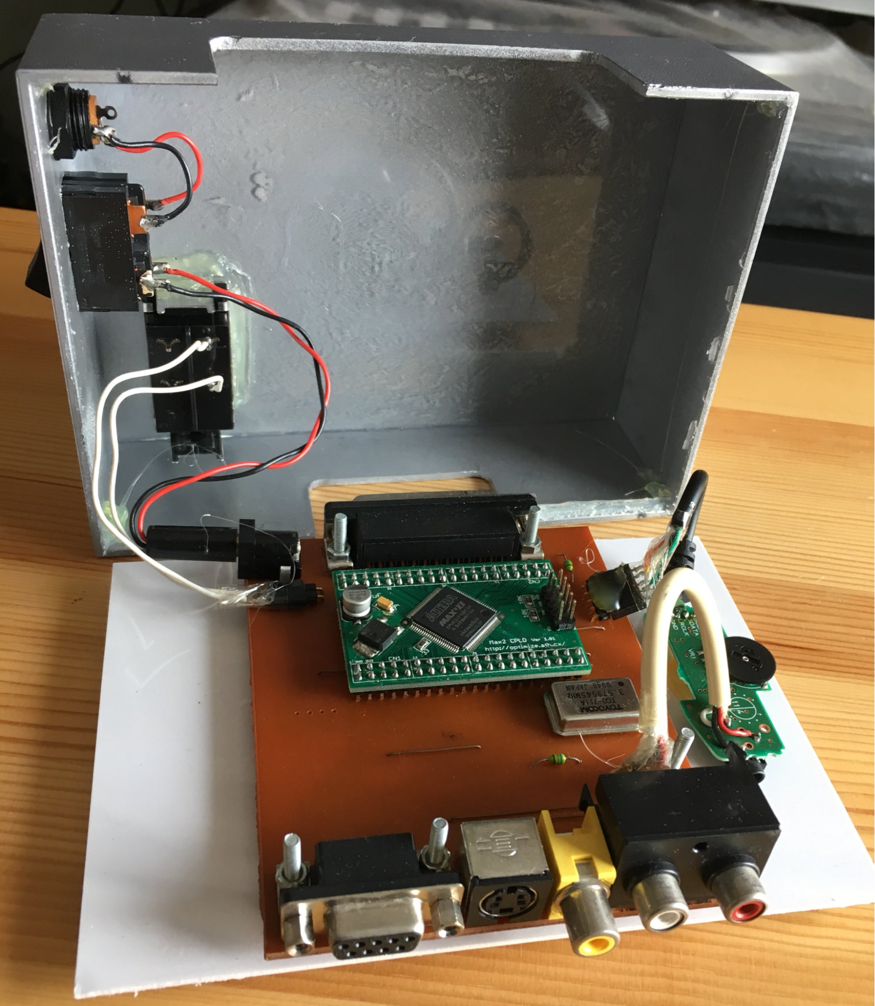
Homemade TVSwan
https://twitter.com/TEMJISO/status/1360785586345287680
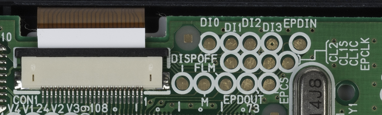
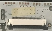
Resolution | 160x152 | |
Colors | 16 Grey level - 4 bits | /!\Not sure about this one |
Buffer size | 24320 | Half if 2 pixels/byte |
Saleae dump | Dump : Screen : Igor pro script : | |
Power | 3V 0.2W 2xAAA | |
Pinout | 24 pin connector ? : Grey 0 ? : Grey 1 ? : Grey 2 ? : Grey 3 ? : Pixel clock ? : HSync ? : VSync | DI0-DI3 : pixel color 4 bits EPCLK : pixel clock ? ? : HSync ? : VSync |
Pixel clock | ||
HSync | ||
VSync |
TODO
Ratio : ?
Resolution : ?x?@?Hz
Timings : http://tinyvga.com/vga-timing/?x?@?Hz
Coordinate : (?,?)
TODO
none
none
None
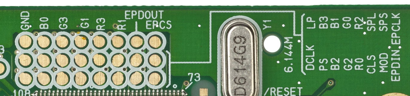
Resolution | 160x152 | |
Colors | 4096 12 bits | 146 on screen |
Buffer size | 48640 | 2bytes per pixel |
Saleae dump | Dump : Screen : Igor pro script : | |
Power | 3V 0.2W 2 AA | |
Pinout | 36 pin connector | Test points R0~3 is 4bit red G0~3 is 4bit green B0~3 is 4bit blue DCLK is the pixel clock SPL is horizontal sync SPS is frame sync |
Pixel clock | 3.06MHz | ≃6.144MHz /2 |
HSync | 120.2KHz ? | |
VSync | 60Hz |
TODO
Ratio : ?
Resolution : ?x?@?Hz
Timings : http://tinyvga.com/vga-timing/?x?@?Hz
Coordinate : (?,?)
TODO
Link : https://blog.gameboymania.com/2014/03/for-old-games.html
https://www.youtube.com/watch?v=qG64QlZuzdg
http://furrtek.free.fr/?a=superngpc
https://www.youtube.com/watch?v=Wr3jlyaQcTM&feature=youtu.be
http://stephens-projects.com/projects/neo-geo-pocket-color-console/
Resolution | 160x160 | |
Colors | 4 colors - 2 bit | |
Buffer size | 25600 | /4 if 4 pixels per byte |
Saleae dump | Dump : Screen : Igor pro script : | |
Power | ||
Pinout | 12 pin connector - Data 0 - Data 1 - Data 2 - Data 3 - Pixel Clock - Line Latch / HSync - Frame Latch / VSync - Frame Polarity/bright control - Power Control | Test points To confirm based on https://circuit-board.de/forum/index.php/Thread/12277-Watara-Hartung-SuperVision-Backlight-Umbau-Hilfe-Infos/ |
Pixel clock | 4MHz | |
HSync | 16.26KHz ? | Based on KevTris info |
VSync | 50.81Hz |
Source : https://github.com/GrenderG/supervision_reveng_notes
TODO
2 fields per frame so, need 2 refresh to draw a frame : similar to draw 320 lines
Ratio : ?
Resolution : ?x?@?Hz
Timings : http://tinyvga.com/vga-timing/?x?@?Hz
Coordinate : (?,?)
TODO
None
https://www.diskman.com/presents/supervision/tvlink.htm
NTSC or PAL
(?) need the 1st version of the Supervision
None
Resolution | 160x102 | Portrait / Landscape mode ? |
Colors | 4096 (12-bit) | 16 colors on screen, apart on Shadow of the Beast (24) |
Buffer size | 32640 | 2 bytes per pixel needed |
Saleae dump | Dump : Screen : Igor pro script : | |
Power | 9V ( 6AA) | |
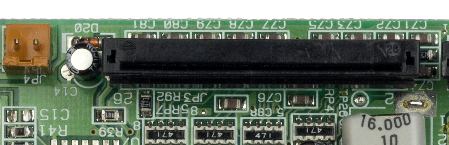
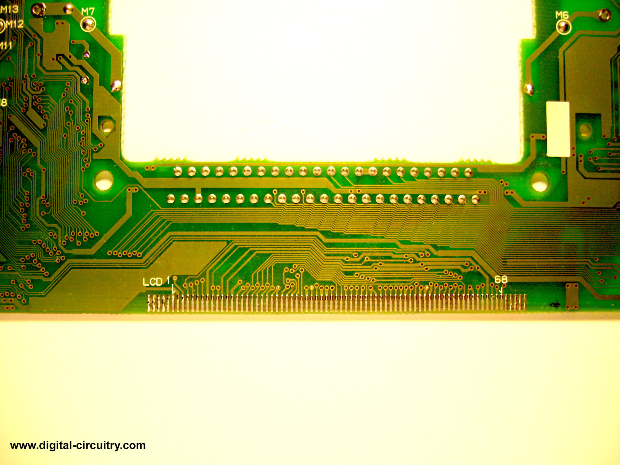
Pinout | ||
Lynx I | soldered cable which make it hard to hack | Test points available in front of several pin soldered, no label |
Lynx II | 26 pin connector 3-8 : Magic LCD Timing Signals 9 : HSync 11 : Pixel Clock A (Idles HIGH) 12 : Pixel Clock An (Idles LOW) 13 : Pixel Clock B 14 : Pixel Clock Bn 15 : Pixel Clock C 16 : Pixel Clock Cn 17 : Pixel Data 1 18 : Pixel Data 3 19 : Pixel Data 0 20 : Pixel Data 2 | |
Pixel clock | ||
HSync | Set by software ? | |
VSync | 50, 60, (70) or 75Hz (or anything) | Set by software TODO : could be changed during gameplay or only on boot ? |
More detail on dynamic frame rate on:
https://archive.org/details/Atari_Lynx_Specification_aka_Handy_Rev_P_Aug_9_1989/page/n9
Pinout source :
https://atarigamer.com/pages/atari-lynx-hardware-notes#lcd_screen
TODO
3 blocks draw at the “same” time, each one with its own clock (hence 3 Pixel Clock) : R, G, B
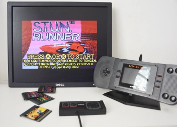
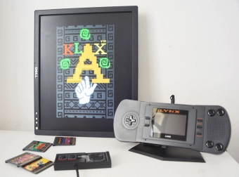
TODO : what about raster effect and color effect explained on http://mag.mo5.com/actu/58759/adaptateur-tv-les-25-ans-lynx/
Dynamic HSync, VSync
Orientation ? (see Klax and Gauntlet)
Ratio : ?
Resolution : ?x?@?Hz
Timings : http://tinyvga.com/vga-timing/?x?@?Hz
Coordinate : (?,?)
TODO
Link : https://atariage.com/forums/topic/230579-tv-out-under-the-christmas-tree-2014/page/4/?tab=comments#comment-3125094
Source : n/a
Price : 95euro
Resolution : n/a @73Hz
FPGA : Xilinx ?
Connection : solder and cable
Remark :
Link : https://atariage.com/forums/topic/202796-lynx-to-vga/
Source : n/a
Price : n/a
Resolution : n/a
FPGA : Cyclone 2 (Altera DE1 board) then lattice machxo2 to handle LCD
Connection : solder and cable
Remark :
Link : https://www.yaronet.com/topics/167987-tv-out-pour-lynx
Source : n/a
Price : 115$
Resolution : 640x480 60Hz
FPGA : Cyclone 2 (Altera DE1 board)
Connection : solder and cable
Remark :
https://www.youtube.com/watch?v=3XsjHWGUVf4&feature=emb_logo
https://www.youtube.com/watch?v=spnS3X-K-o4
https://www.youtube.com/watch?v=bsCzxh4wcdg
https://www.youtube.com/watch?v=VT7PHMNbB2o
https://atariage.com/forums/topic/282545-consolized-atari-lynx-1-with-mcwill-vga-controller/
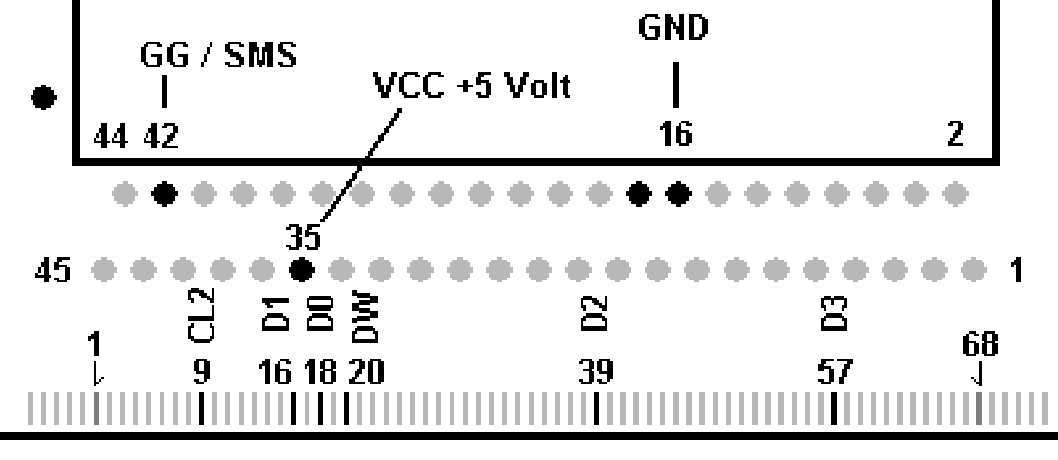
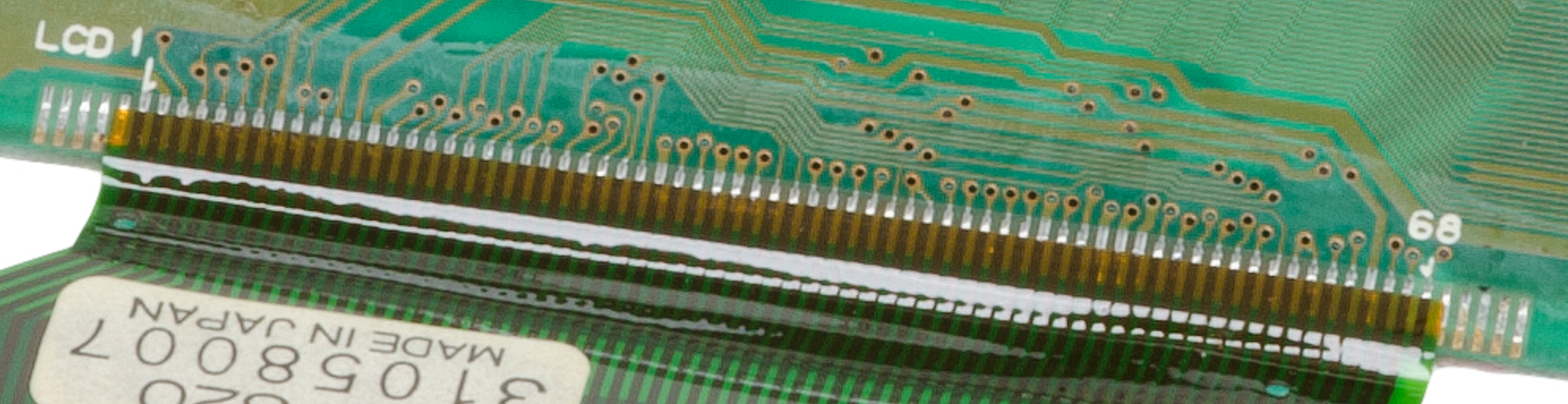
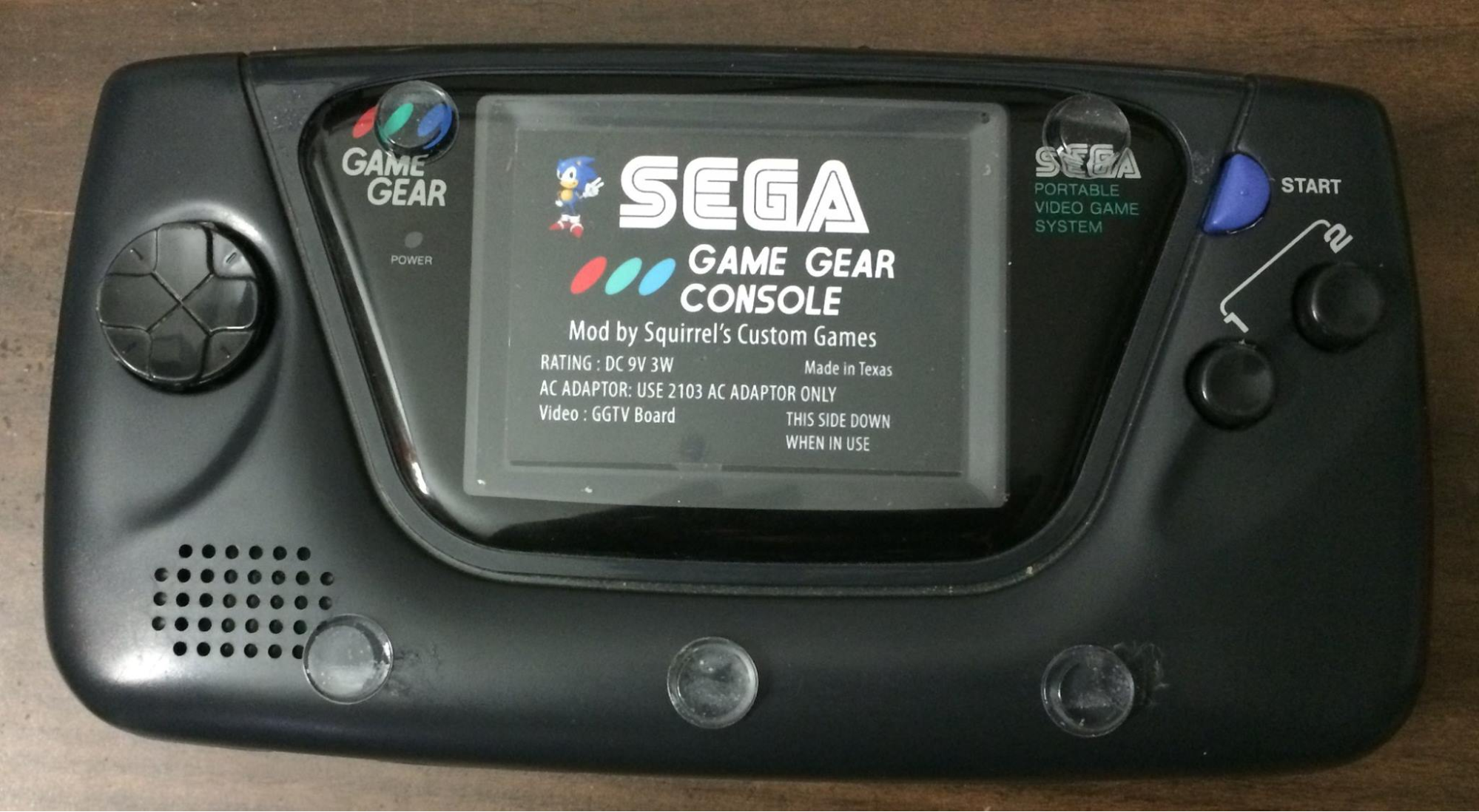
Resolution | 160x144 | |
Colors | 4096 - 12bits | 32 on screen |
Buffer size | 46080 | 2bytes per pixel |
Saleae dump | Dump : Screen : Igor pro script : | |
Power | ||
Pinout 1 ASIC 2 ASIC V0 Majesco VA4 VA5 | 68pin soldered to PCB
18: D0 16: D1 39: D2 57: D3 20: DW 9 : CL2 | Test points available before each cable pin solder, no label |
Pixel clock | ||
HSync | ||
VSync |
TODO
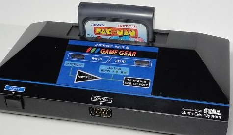
https://www.smspower.org/forums/post68683#68683
SMS/GG mode
Scaling
https://www.smspower.org/forums/9562-GameGearSMSModeVideoScaling
Ratio : ?
Resolution : ?x?@?Hz
Timings : http://tinyvga.com/vga-timing/?x?@?Hz
Coordinate : (?,?)
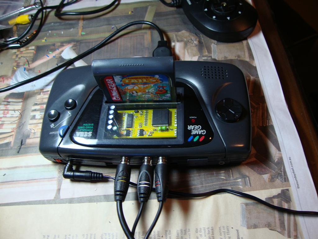
A lot of projects are based on GGTV by Viletim
https://etim.net.au/ggtv/ggtv.htm
If you want to ouput composite, it’s the right way to do
If you want VGA, it”s not ;)
Link : https://www.smspower.org/forums/11931-ConnectYourGameGearToATV
Source : n/a
Price : n/a
Resolution : n/a
FPGA : n/a
Connection : solder
Remark :
Link : https://www.retromodding.com/products/mcwills-sega-game-gear-lcd-upgrade
Source : n/a
Price : 120$
Resolution : n/a
FPGA : Xilinx ?
Connection : solder
Remark :
Link : http://gglcd.bufsiz.jp/?utm=rc&page=gglcd
Source : n/a
Price : n/a
Resolution : n/a
FPGA : n/a
Connection : solder
Remark :
Link : http://stephens-projects.com/projects/gghdmi/
Source : n/a
Price : n/a
Resolution : 1280x720p
FPGA : n/a
Connection : solder
Remark :
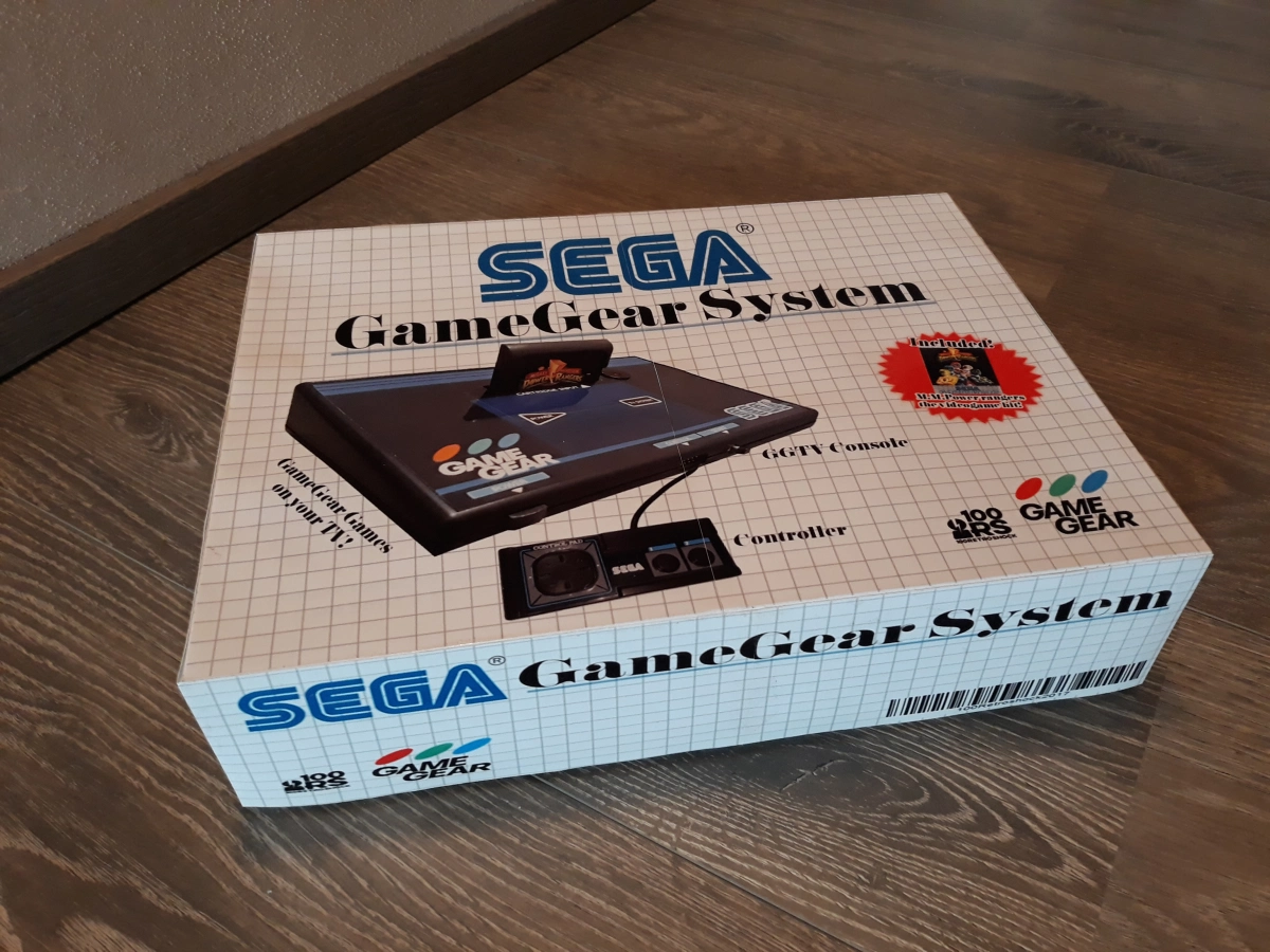
GGTV by Sega
Include a Mark3 adapter
http://www.lcv.ne.jp/~mgs1987/sega/gg.html
http://www.lcv.ne.jp/~mgs1987/sega/gg2.html
http://www.lcv.ne.jp/~mgs1987/sega/gg3.html
http://www.lcv.ne.jp/~mgs1987/sega/gg4.html
http://www.lcv.ne.jp/~mgs1987/sega/gg5.html
http://www.lcv.ne.jp/~mgs1987/sega/gg6.html
http://www.lcv.ne.jp/~mgs1987/sega/gg7.html
http://www.lcv.ne.jp/~mgs1987/sega/gg8.html
http://www.lcv.ne.jp/~mgs1987/sega/gg9.html
http://www.lcv.ne.jp/~mgs1987/sega/gg10.html
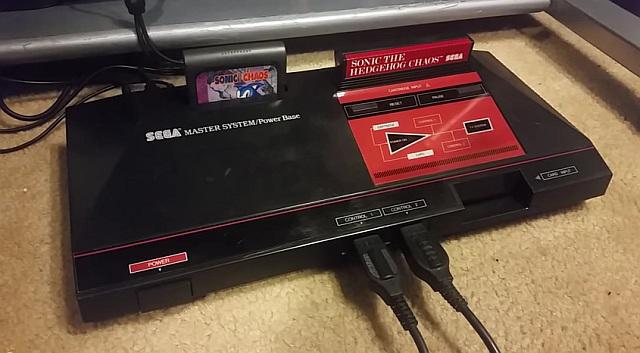
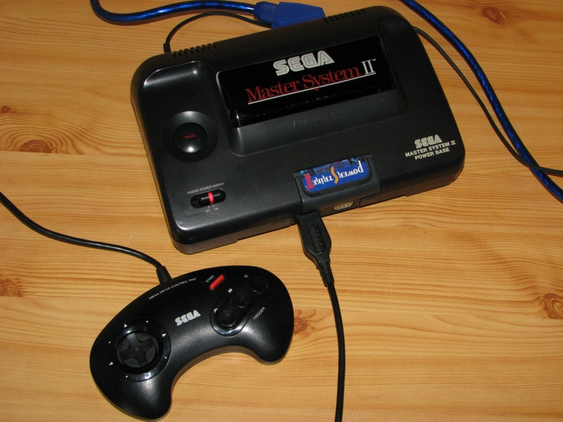
Updated SMS with updated GG inside a SMS1, with GGTV
https://www.youtube.com/watch?v=FQLIq6mjjCk
https://vintageisthenewold.com/custom-sega-master-system-with-built-in-game-gear-cart-slot/
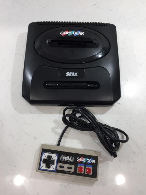
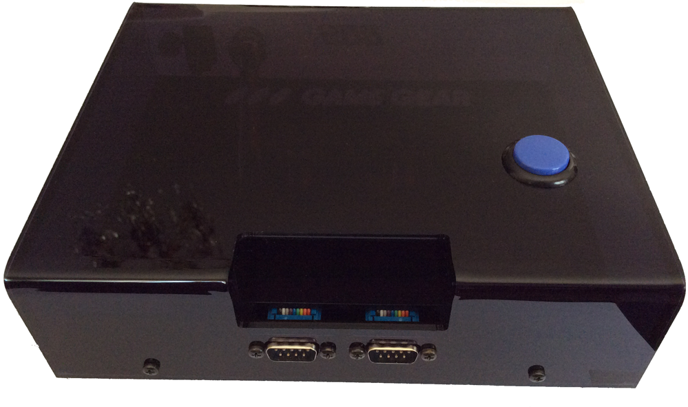
GGTV Console
GGTV powered
https://16picsel.wordpress.com/category/game-gear/
Based on GGTV
https://www.smspower.org/forums/post59589#59589
GG in a SMS
https://forums.sonicretro.org/index.php?threads/3-years-ago-i-sent-tmee-a-game-gear-to-mod.36267/
GG in a MD2
Based on GGTV,
Base on GGTV
https://www.beharbros.com/consolized-game-gear
Based on GGTV
https://imgur.com/t/gaming/xXmlE
Resolution | 160×144 | |
Colors | 4 grayscale (2 bit) | |
Buffer size | ||
Saleae dump | Dump : Screen : Igor pro script : | |
Power | 4x AA batteries AC adapter 6 VDC / 300 mA | |
Pinout | ||
Pixel clock | ||
HSync | ||
VSync | 59.732155 Hz |
TODO
From Wikipedia but without really clear source
“The Video Display Controller of the Mega Duck/Cougar Boy has one special feature, the display logic uses two "display planes" that are used to create parallax scrolling backgrounds, as if the picture is drawn on two sheets of which the top sheet is partly transparent.”
Ratio : ?
Resolution : ?x?@?Hz
Timings : http://tinyvga.com/vga-timing/?x?@?Hz
Coordinate : (?,?)
TODO
None
None
None
Evan Amos for all his awesome HD pictures
https://commons.wikimedia.org/wiki/User:Evan-Amos
Furrtek for everything he made and shared (and still doing)
RetroRGB for reviewing a lot of existing mods, from user and engineer point of view
McWill for his awesome LCD upgrades which, when you know how to read installation manuals, let you learn a lot of things...since he rarely shares his technical details, unfortunately ($$).