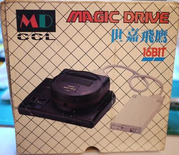
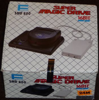
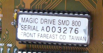
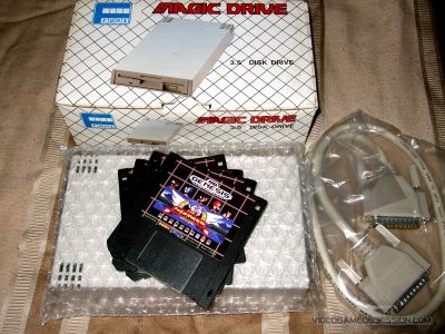
The Super Magic Drive is probably most known of the Genny backup device.
It allows you to
dump a game to a rom on floppy disk
play a game from a rom on floppy disk
dump a game to a rom on PC
load a rom from PC
load/save SRAM (not all versions)
load/save VRAM (not all versions)
SMD is available in 8M, 16M, 24M or 32M model.
For more general details, you should check Sega Retro. They wrote a very interesting article on the Super Magic Drive.
Unfortunatly, the SMD is also known for its main default : it uses a battery to keep save game. This battery is a nightmare because it leaks !
If you didn't remove the battery before it leaks, you could be sure your SMD will soon or later break because the PCB will be damaged.
This page will so focus on how to repair, update and hack this device.
It completes Charles' document.
All the informations given here come from wonderful people on SpritesMind's and Tototek's forum.
Thanks to Charles, Mark, Mystic_Merlin, LocalH and the others !
The SMD is very easy to open (4 standards screws!).
It's so possible to access the PCB and urgently remove the battery fix any damage.
The good news is they didn't use CMOS part.
The bad news is you'll need some wires to fix traces the battery corroded.
The heart of the system is not, for me, the bios but the EPLD.
We haven't the source so if you break it, you'll be unable to reprogram a new one with the correct gates.
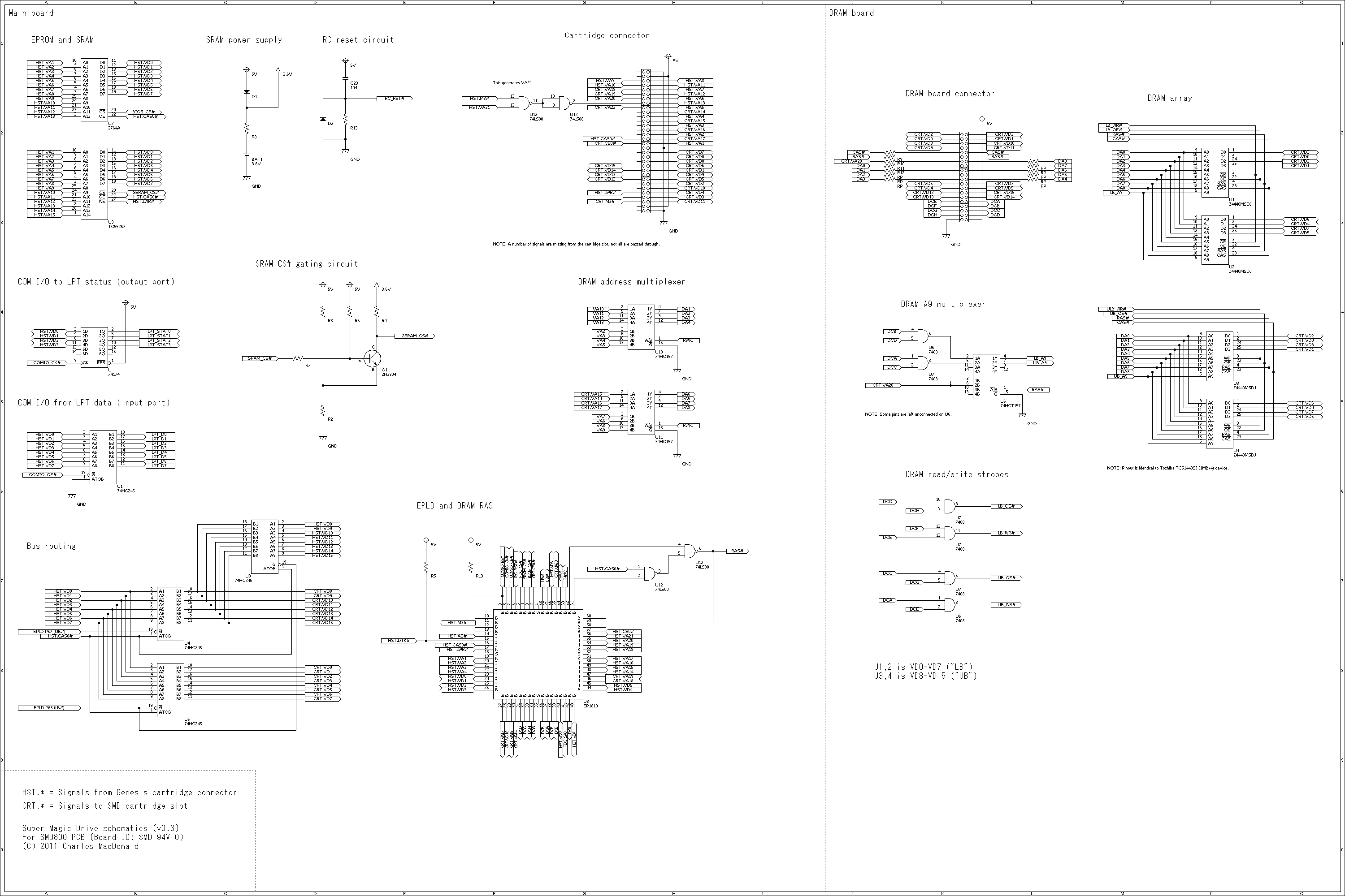
Schematics
Charles did a wonderful work tracing the PCB.
We now have a schematic for reference. (Thanks again Charles!!!)
Note : there is at least 2 points I'm personnaly not sure they are right so be careful
CRT.VD10 and CRT.VD11 are switched: U4's B3 go to Connector's pin 7 and U4's B4 to pin 5
CRT.VA20 is on pin 8 of the cart connector, not pin 7
Components
Each component has an ID.
Here is what I found on my own SMD :
U1
SN74LS245N
Octal Bus Transceivers
U2
HD74LS174P
Quad. D-type Flip-Flops with Clear
U3
HD74HC245P
Octal Bus Transceivers (with 3-state outputs)
U4
HD74HC245P
Octal Bus Transceivers (with 3-state outputs)
U5
MCCS3201FN
Floppy Disk Controller
U6
HD74HC245P
Octal Bus Transceivers (with 3-state outputs)
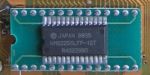
U7
???
8K x 8 CMOS EPROM 150ns
BIOS (eprom window MUST be covered by sticker to avoid erasing)
U8
EP1810LC-45
CPLD 900 gates
the only thing you can't fix
U9
M5M5256BP-10
256K SRAM
U10
HD74HC157P
Quad. 2-to-1 line Data Selector/Multiplexer
U11
HD74HC157P
Quad. 2-to-1 line Data Selector/Multiplexer
U12
HD74LS00P
Quadruple 2-Input Positive NAND Gate
?
J1
SUB25
COM I/O
PC
J2
SUB25
DISK I/O
Floppy
J3
25Pin SUB25
bridge ?
J4
2x32 Edge connector
Cartridge
J5
2x32 header
MD
J6
2x20 female
DRAM board connector
?
RP1
A 472J
4.7KO - 5% 8 pin common
RP2
empty
RP3
B 330J
33O - 5% 8 pin isolated
RP4
B 330J
33O - 5% 8 pin isolated
RPx
A 222J
2.2KO - 5% 9pin common
mixed with U6
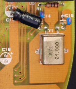
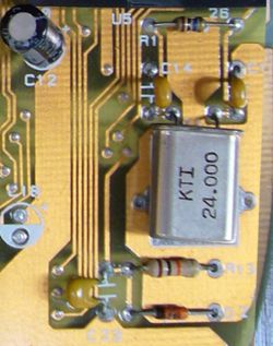
Y1
KTI 24.000
Crystal 24MHz
CL = 5pF + C14/2 = 10pF
BT1
3.6V NiCd
Battery
to remove!
Q1
2N3904
NPN switching transistor
?
D1
1N4 148
Diode
D2
1N4 148
Diode
?
C1
2.2μF 25V
Electrolytic
C2
0.1μF
Ceramic (104)
C3
0.1μF
Ceramic (104)
C4
0.1μF
Ceramic (104)
C5
empty
C6
0.1μF
Ceramic (104)
C7
0.1μF
Ceramic (104)
C8
empty
C9
0.1μF
Ceramic (104)
C10
empty
C11
empty
C12
2.2μF 25V
Electrolytic
C13
0.1μF
Ceramic (104)
C14
10pF
Ceramic (100 A1J 102 R4M)
for oscillator
C15
10pF
Ceramic (100 A1J 102 R4M)
for oscillator
C16
2.2μF 25V
Electrolytic
C17
0.1μF
Ceramic (104)
C18
empty
C19
0.1μF
Ceramic (104)
C20
0.1μF
Ceramic (104)
C21
0.1μF
Ceramic (104)
C22
2.2μF 25V
Electrolytic
C23
0.1μF
Ceramic (104)
?
R1
10MΩ - 5%
Brown Black Blue - Gold
for oscillator
R2
1KΩ - 5%
Brown Black Red - Gold
R3
2KΩ - 5%
Red Black Red - Gold
R4
2.2KΩ - 5%
Red Red Red - Gold
R5
2.2KΩ - 5%
Red Red Red - Gold
R6
10KΩ - 5%
Brown Black Orange - Gold
R7
220Ω - 5%
Red Red Brown - Gold
R8
2.2KΩ - 5%
Red Red Red - Gold
R9
33Ω - 5%
Orange Orange Black - Gold
R10
33Ω - 5%
Orange Orange Black - Gold
R11
33Ω - 5%
Orange Orange Black - Gold
R12
33Ω - 5%
Orange Orange Black - Gold
R13
3KΩ - 5%
Orange Black Red - Gold
R13
10KΩ - 5%
Brown Black Orange - Gold
for oscillator
Revision
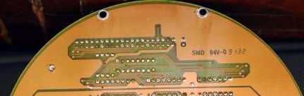
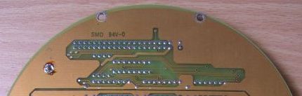
At least 2 PCB versions exist
You can identify them with the RC reset circuit (R13,C23 and D2) : it's missing on v1.
Or throught the PCB ID : it's the same but at right on v1.
Thanks to Mystic Merlin, we know the first one (8M, sold by CCL) missed this RC reset circuit.
You will also see some differences like
U9 in DIP or SOP package (with adapter)
U9 replaced by a CXK58256P-10 or a HY62256ALP-10
I think it's only a budget issue : components available at time of production were cheaper than others one.
I won't say it's specific to a PCB version.
I also saw a PCB with U3, U4 and U6 socketed...I don't know if it was a genuine PCB or a PCB modded/fixed.
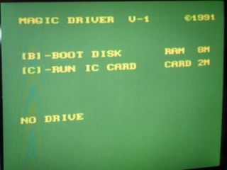
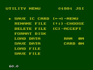
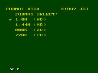
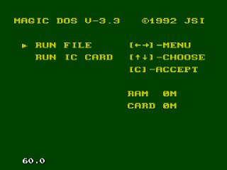
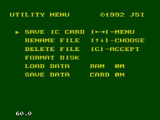
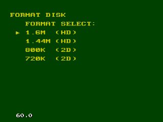
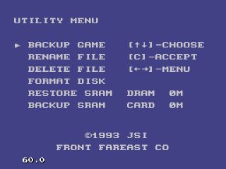
►BIOS
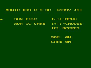
The BIOS is the software which handle all the useful functions you bought the SMD for ;)
It runs like any others Genny games the first time you switch on the Genny with a SMD plugged in.
The fun part is it was written in Z80, so run in SMS compatibility mode.
You so could the SMD like a SMS cartridge with a lot of functionnality.
We actually knew 5 differents versions of this BIOS : 4 were already dumped and are already available on Sega Retro page.
The good news is the BIOS is stored on a eprom plugged in a socket. You can so easily remove it and plug a fresh 8K eprom like a standard 27C128 with the BIOS you want.
It seems the upper the serial number, the upper the BIOS version
But which BIOS do you want/need ? The lastest one ? not sure because they removed some interesting functionnalities...
Here is the details of each BIOS, what they do and don't to help you choose the "good" one.
I also hope to share with you a way to make your own BIOS, with the functionnalities you want only (and perhaps new ones!).
?? I'm not sure every SMD support any BIOS. Based on this post, not all versions could handle 24M games without hardware modification (or special DRAM board)...so be careful with BIOS 4 ??
on startup, load cart on DRAM and launch it. You're so able to test your DRAM this way.
For more info, check my disassembly (include IDA script to fix the disassembly yourself if needed)
Change its name again and :
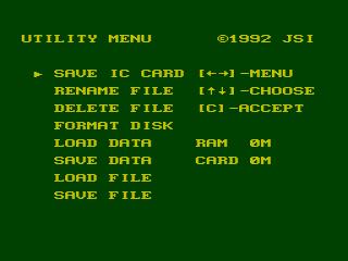
handle multifile (status = bit 6 of smdheader)
more friendly messages ( xxx OK)
ask for floppy if not found
on startup, load cart on DRAM only, it no longer launches it.
Unfortunatly, this version removes an useful feature for developer :
save/load VDP...from menu, since it's still working on PC command (command 2 and 3)
For more info, check my disassembly (include IDA script to fix the disassembly yourself if needed)
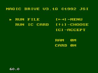
Add the load file in DRAM and dump file from DRAM.
Useful for developers !
It's my bios of choice
For more info, check my disassembly (include IDA script to fix the disassembly yourself if needed)
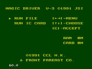
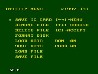
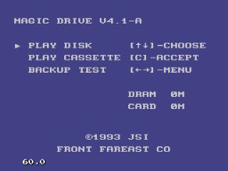
Get back its name and :
support for larger game and new size of pages (128k vs 16k), needed to support 24M+ (?)
change colors pal (no longer old school's green)
new item on main screen : BACKUP TEST which run cart game in DRAM (like the hidden feature in 3.1G)
use 'SRAM' and not 'DATA', at last
add a new PC command 6 : launch data in DRAM, you're now able to load data (command 0) then launch it (command 6)
better multi file support (?)
Unfortunatly, this version removes a lot of features :
save/load VRAM PC command 2 and 3
the more friendly messages where removed
button at start feature added in 3.1G (and already updated in 3.3) disappeared, because it's now possible to do it from menu
For more info, check my disassembly (include IDA script to fix the disassembly yourself if needed)
CUSTOM
A lot of features where added/removed between each version.
Of course, the main reason is the 8K limit of the BIOS size.
I don't think there is way to increase the BIOS size limit but I know it's totally possible to choose yourself which features is good for your need.
Every (but the first one) bios was dumped and disassembled so it's only a matter of mixing the asm code of each one the way you want.
All you need is a Z80 assembler and the piece of codes to include.
It's not already done but it's on my to-do list right after I fix my SMD (^$*?^ battery!) so follow my blog and the forum for more news about this.
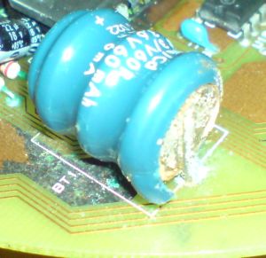
►Battery
If you SMD doesn't work anymore, this is the FIRST (if not only) thing to check :
They used NiCd battery to keep game data (scores in EA sport games or savegame in RPG) even when the SMD isn't powered.
The main problem of this kind of battery is how they leak !
First, this leak is VERY toxic.
Second, it eats PCB.
So yes, if the battery leaks, it's slowly killing your SMD.
What ? You didn't remove it yet ?
Note, the battery is a rechargeable one. You can't replace it with standard battery (unless some hardware mod).
Fix the damage
Even if you removed the battery, you HAD to clean the leak.
I'm one of these fools who only removed it...I now have a dead SMD, waiting for medical help !
A NiCd battery leaks chemical ACID, so don't use lemon to clean !
The only way is to use sodium bicarbonate mixed with water.
Take a toothbrush and apply this solution on the corroded part of the PCB.
Wait some minutes (you should see some 'bubbles') and clean again with the toothbrush.
Use some clean water and dry it.
A SMD owner used white vinegar and water...I'm not sure it's perfect for this but thanks for his step by step guide.
Replace it
The battery is 3.6V 60mAh so you could find a replacement part on eBay or Tototek.
If possible, please, use a NiMh rechargeable battery, it's less toxic.
Be careful, the battery will be charged using a 5V / 2mA line.
To use it, you needs the same cable as for PC connection (see COM I/O) and an externel AC adapter of at least 5V but not greater than 12V.
It also must supply a current of 1A (500mA isn't enought for a FDD).
A MD1 AC adapter fits perfectly !
You'll rarely find a SMD with a working floppy drive.
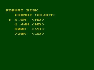
There are 3 ways to fix it :
change the voltage regulator
change the drive
make your own external drive
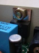
Voltage regulator
The voltage regulator's task is to convert anything from 8V to 12V to a regulated 5V.
It's a common 7805.
If the drive doesn't power on or the SMD gives you back "No floppy", it may be because the voltage regulator is faulty.
If you need to change it, be careful to take 1A or 1.5A, not the more common 0.5A!
Only TO-220 package will work because the voltage regulator is grounded throught its head, screwed on the metal rear panel.
Also, be carefull with the small trace on the back of the PCB : it's the VIn and it sometimes get lost when you solder a new one. Sorry for the quality but it's the only one I have since mine lost this trace !
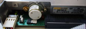
Floppy drive
The original drive is a TEAC FD-235HF.
In fact, there is several FD-235HF series, this one is a TEAC FD-235HF 4291-U.
Very important if you need to fix the jumper settings.
In theory, there is no reason this adapter won't work on any FDD model, but I didn't try it yet. Coming soon : test with other drives / brand right after I fix my voltage regulator.
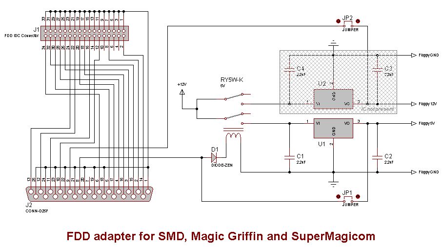
DIY disk drive
If you haven't an original Magic Drive, you can try to make you own
2 ways : a copy of the original one or a less expensive one
The original uses a relay (and some capacitors) to power drive on only when needed.
With the help of Charles, I made a schematic of the Magic Drive adapter.
The less expensive one only needs a 5V 1A AC adapter, connectors and wires.
It doesn't use a relay and so the floppy drive is always under power.
An exemple was posted on this blog.
►COM I/O
You can send/receive data to/from a SMD connected to your PC.
To do this, you need a PC with a LPT port, the cable and software to "talk" with the SMD.
You need a Centronics DB25 cable, you can also use the floppy-cable.
If you have no cable you can simple build one by connecting all pins 1:1.
DATA 0     <-->     Data 0
DATA 1     <-->     Data 1
DATA 2     <-->     Data 2
DATA 3     <-->     Data 3
DATA 4     <-->     Data 4
DATA 5     <-->     Data 5
DATA 6     <-->     Data 6
DATA 7     <-->     Data 7
STROBE     <-->     STROBE
BUSY     <-->     BUSY
GND     <-->     GND
....
Since the SMD bios run on SMS mode, the SMD would not work on a Genesis 3.
Hopefully, for some revisions of the Genesis 3 mainboard, you could reactivate the SMS compatibility mode throught a wire from ASIC pin 43 to connector pin B30.