Page 13 of 58

Posted: Thu Sep 11, 2008 12:49 pm
by Eke
Ahh..I remember I had this problem as well when I used MAME core in Regen (you can still hear it in 0.77, the last version to use MAME core). I remember that it was related to SSG-EG. You should look there.
thanks, indeed it was a problem with the SSG-EG invert flag: I reseted it when key-off occurs at Nemesis explained but the game will set it again after KEY OFF by writing 0xFF into the SSG-EG register before later setting it back to 0x00 before next KEY ON), which will activate SSG-EG enveloppe type during this time.

Also, the write will mess up the invert flag status which should not be set during Release Phase.

I fixed it by checking we are not in Release Phase before eventually inverting the output in SSG-EG mode
if ((SLOT->ssg&0x08) && (SLOT->ssgn&2) && (SLOT->state > EG_REL))
out ^= MAX_ATT_INDEX;
but I'm wondering if this write to SSG-EG register is intentional and should really affect the Release Phase ? Maybe SSG-EG register state is latched on Key ON only and can not be affected during Enveloppe update ?
Also, what would happen if you write the register during Decay or Substain phase ?

Anyway, I don't think this game use SSG-EG intentionnaly in any way, it just has no sense in setting it to 0xff then to 0x00

Posted: Thu Sep 11, 2008 1:41 pm
by Nemesis
I still need to do tests to determine when various register changes take effect. I think you'll find most of the decisions about SSG-EG are only made when changing between envelope generator states, but I think it's quite possible that toggling the SSG-EG enabled state during the release phase (or the sustain and decay phases) could cause the 6x multiplier effect on the attenuation increment to be toggled on or off as the phase progresses. Perhaps this is what they are trying to do in Alisia Dragoon? They'd have to control the timing in software, but if it was done correctly, you could effectively achieve two stages of release, with the second stage being 6 times slower than the first.

Posted: Thu Sep 11, 2008 2:13 pm
by AamirM
Hi,

My guess would be that it toggles between 4x and 6x multiplier rather than off.

stay safe,

AamirM

Posted: Sat Sep 13, 2008 1:08 am
by Snake
TulioAdriano wrote:I find it quite hard to undestand why he doesn't post here... :( :?:
Well one reason would be that I didn't know of it's existance ;) I've spent the best part of the last 4 years being almost completely absent from the internet.

And, yeah, life is more than a bit evil right now. I won't go into it here.

Interesting stuff. I think I have most of it correct, but I've forgotten more about the YM2612 than I remember. There were a few things I knew weren't correct but I think I've already fixed most of them. Really should release a new build at some point. And cross reference with these documents.

For the record I've not been intentionally hiding any findings, Stef will tell you I sent him the source for an early Kega implementation, but he likes to try to figure things out on his own :) It's only more recently that people have been asking, and I've been not very good at remembering to look things up. But if there's anything I can add to the discussion I shall do so.

Yes, most of what I found was done via hacking at the hardware rather than documentation. It also helped that I already understood how FM synthesis worked. But I'd kill for a YM2612 on a PC card.

The CSM stuff is news to me, though. I haven't really looked at this since 1997, when I was talking to Tatsuyuki Satoh (original MAME core, and the one I think Stef based his on) - he has some japanese documents which suggested CSM mode was useless without the timer interrupts. Timer A would do key ON, and you'd have to key it OFF again yourself in an interrupt. We tried to figure it out but I eventually decided it'd be pretty useless on the Genesis.

The only thing (as far as I remember) that I still want to know is this: The YM2612 (apparently, and I don't remember where I found this) output DAC has one bit less than it would normally need. Something is done to remove one bit before it goes into the DAC. It appears to be some sort of compression/scaling which results in values close to silence being much louder. If you can figure that out I'd be very interested.

I no longer have access to my hardware so I can't do tests anymore :(

Posted: Sat Sep 13, 2008 1:36 am
by King Of Chaos
Welcome to the party Snakey. ;)

The circle is now complete...

Posted: Sat Sep 13, 2008 4:09 am
by Nemesis
Hi Snake, I was hoping you'd drop by at some point. Welcome to the forum. :)
The CSM stuff is news to me, though. I haven't really looked at this since 1997, when I was talking to Tatsuyuki Satoh (original MAME core, and the one I think Stef based his on) - he has some japanese documents which suggested CSM mode was useless without the timer interrupts. Timer A would do key ON, and you'd have to key it OFF again yourself in an interrupt. We tried to figure it out but I eventually decided it'd be pretty useless on the Genesis.
I get the feeling CSM is one of those functions that's probably implemented a little differently across a variety of chips, possibly even within the OPN line. Those documents he had may have been correct for another Yamaha chip. It would be nice to have a look at them, but I guess he never scanned them in.
The only thing (as far as I remember) that I still want to know is this: The YM2612 (apparently, and I don't remember where I found this) output DAC has one bit less than it would normally need. Something is done to remove one bit before it goes into the DAC. It appears to be some sort of compression/scaling which results in values close to silence being much louder. If you can figure that out I'd be very interested.
I think I know the answer to that one. :)

The YM2612 has an embedded YM3016 DAC. I know that for sure. I also obtained a datasheet for the YM3016 DAC when I got the YM2608 documentation, but unfortunately, the YM3016 datasheet is also in Japanese, and I haven't found an English version. Fortunately, that doesn't matter one bit, as I've noticed the YM3015 is identical to the YM3016, with the exception that it takes a 12V input rather than the 5V input the YM3016 uses, and there's a YM3015 datasheet publically available in English. If you look at the datasheets, they contain the exact same information, with only the operating voltages differing.

Here's the YM3016 datasheet in Japanese:
http://nemesis.hacking-cult.org/MegaDri ... M3016J.pdf

and here's the YM3015 datasheet in English:
http://nemesis.hacking-cult.org/MegaDri ... YM3015.pdf

Many other DAC's in the YM301X line like the YM3012 and YM3014 take the input to the DAC in a floating point format, with a 3-bit exponent and a 10-bit mantissa. The YM3015 and YM3016 are different in that they take their input as a 16-bit integer value in either binary or 2's compliment form. Internally, the DAC still converts that 16-bit input into a 3-bit exponent and 10-bit mantissa before using it however. Looking at the YM3015 datasheet, here's a block diagram of the internal operations the DAC performs:
Image

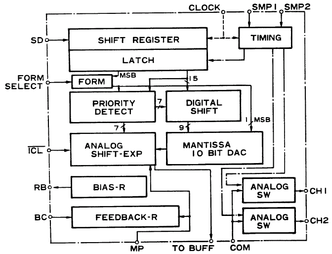
SD is the 16-bit serial data input, which comes from the accumulator in the case of the YM2612. The "Form Select" line switches between binary and 2's compliment mode. The "Form Select" and "ICL" lines are also tied to bits in the test register.

This internal conversion process means that although the output from the accumulator is 16-bit (with 14-bits of meaningful data from the operator unit), internally, the DAC converts it back to a 10-bit mantissa and 3-bit exponent before generating the analog output, so there is the potential for some loss of precision within the DAC unit. I haven't had a good look yet at the effects of the internal floating point conversion in the DAC on the precision of the signal output. There's also still a question in my mind about what the YM2612 sets the lower 2 bits of the 16-bit accumulator output to. They might not simply be 0.

I was going to look at the DAC last, once I've finished examining the other components of the YM2612. I've also noticed the extreme jump between low volume and silence though. I'm sure the answer to that behaviour lies in the DAC.

Posted: Sat Sep 13, 2008 5:55 am
by HardWareMan
Nemesis wrote:I was going to look at the DAC last, once I've finished examining the other components of the YM2612. I've also noticed the extreme jump between low volume and silence though. I'm sure the answer to that behaviour lies in the DAC.
I confirm that! A very noticeable ladder effect is exist.
Image
Image
Image

Posted: Sat Sep 13, 2008 6:13 am
by Snake
Nemesis wrote:The YM2612 has an embedded YM3016 DAC. I know that for sure.
Ok, from what I know, *most* chips that have an embedded DAC do indeed use that one. But in the YM2612? It's 9 bit instead of 10... Unfortunately I can't remember where I got this info.

Posted: Sun Sep 14, 2008 12:04 pm
by Nemesis
Well, looking at the YM3016 datasheet, the 10-bit mantissa actually includes the sign bit. Traditionally when taking about floating point formats, the sign bit would be counted separately from the mantissa, so maybe that's where that came from.

If the embedded DAC in the YM2612 did use a different floating point format, it would have to be an unknown variant. Every Yamaha YM301X DAC I've heard of uses the same floating point representation.

I'll do tests on the DAC later on to see if I can confirm the mantissa size. I'm pretty confident in the assertion that the YM2612 has an embedded YM3016 though.

Posted: Wed Sep 17, 2008 7:05 am
by AamirM
Hi,

@Snake

I've been busy lately myself but I noticed that Kega has lower level in some places than all other emu and I was wondering why was that (if you remember of course). It noticeable in Spiderman - Spearation Anxiety intro music. Also the first stage sound of Sonic And Knuckles sounds a bit different from other emus.

stay safe,

AamirM

Posted: Fri Sep 19, 2008 8:59 pm
by Snake
AamirM wrote:I was wondering why was that (if you remember of course).
Hmm, I have no idea, I'd have to see exactly what those games are doing, and even then that might only give me an *idea* why. When I get the chance I'll check it out and see if I can hear what you're reporting.

Ok, quick postage of some interesting bits I missed earlier.
TmEE wrote:Kega won't play the currently played sample on the channel in next one when you change Left/Right reg so you can get nice and clean stereo sample playback
Heh, that's interesting :) I guess the hardware doesn't allow you to switch channels that fast. Admittedly something I never tested, because I didn't expect anybody to ever do that. What happens on the real hardware? Do you have a recording?
Eke wrote:at least , this was not correctly emulated in emulators (counter was reloaded every time the timer load value was changed)
It's right in Kega. Or if it isn't, it should be, because I knew this :)
TmEE wrote:One interesting thing : Hellfire, on MD2s (and other systems with Sega implementation of YM2612 in the ASIC) the music plays half as slow as it would on Yamaha discrete YM2612 chip
Also interesting. I remember this game giving me trouble back in the very early days of KGen. One thing it does is spam the living hell out of the YM2612, repeatedly writing registers that haven't changed. I don't remember if it checks the status to see if the chip is busy between writes - but maybe it does, and those writes take a bit longer on the different chip? (or, maybe the newer chip forces a delay if you write to quick?) It's possible it wastes so much time with all this spamming that it misses an interrupt or timer interval. That'd explain why it runs at half speed.
Nemesis wrote:I know Steve Snake mentioned once that SSG-EG "doesn't always behave like it should" in the YM2612, but I haven't found any indication of that so far.
Yes, I can't remember now what that was. But I was definitely doing some tests on it and getting rather odd and unexpected results back. At the time I couldn't make any sense of it, and I meant to look at it again later. I don't know if it's actually important, i.e. if any games try to do what I was doing.
Nemesis wrote:For the record, I haven't finished working on this chip. Not by a long shot.
Heh, eight years on and off for me, and I'm not done yet either :)
Nemesis wrote:Operators which directly modulate another operator can simply have their output fed directly into the input for the next operator and they never need to be stored.
Aha. The document you found mentions there is only one operator. Incorrect. There are two, running in parallel. It simplifies the hardware design. This is the reason for the 'odd' operator numbering (1,3,2,4) in the registers. It also means that in most algorithms, an operator may need input from another one that's running parallel with it, and thus not ready yet. And so... it uses the previous output of that operator. This is what all the MEM stuff in Mame is all about, and it's correct.

Posted: Sat Sep 20, 2008 10:24 am
by Nemesis
Aha. The document you found mentions there is only one operator. Incorrect. There are two, running in parallel. It simplifies the hardware design. This is the reason for the 'odd' operator numbering (1,3,2,4) in the registers. It also means that in most algorithms, an operator may need input from another one that's running parallel with it, and thus not ready yet. And so... it uses the previous output of that operator. This is what all the MEM stuff in Mame is all about, and it's correct.
Yeah, once I had a closer look at the MAME implementation, I guessed that's what they were emulating. I haven't verified that on the hardware yet, but I expect I'll find it's correct once I test for it.

I must say however, the self-feedback implementation still baffles me. MAME adds the last two samples together to build the self-feedback modulation value. This seems to be correct, but I can't figure out why it's correct, or rather, why the guys at Yamaha chose to implement it this way. Of course, there's no rule that says self-feedback has to be implemented in any particular way. Maybe they found this method "sounded better". It does produce a better saw-tooth when FB=5. I should probably stop wasting time on it and look at something else.

Posted: Sat Sep 20, 2008 11:07 am
by Nemesis
Also interesting. I remember this game giving me trouble back in the very early days of KGen. One thing it does is spam the living hell out of the YM2612, repeatedly writing registers that haven't changed. I don't remember if it checks the status to see if the chip is busy between writes - but maybe it does, and those writes take a bit longer on the different chip? (or, maybe the newer chip forces a delay if you write to quick?) It's possible it wastes so much time with all this spamming that it misses an interrupt or timer interval. That'd explain why it runs at half speed.
I've got a way to sample cycle-accurate measurements for the busy flag on the separate YM2612 BTW. I saw on a pinout somewhere that the supposed "unused" pin 10 is really a "TEST" pin. I've confirmed this is correct, and that what this pin actually does is indicate the current "busy" status of the chip. Yamaha could have used this pin to drive their tests on the chip, without having to read the status register to know when they could send each successive write.

I'm getting a logic analyzer in the coming months, which will make it easy to measure the number of cycles the chip remains in a busy state. It wouldn't be as easy to test the busy status of the embedded YM2612, but once I've got the exact numbers for the real chip, it shouldn't be too hard to determine whether the embedded chip is different at the very least.

Posted: Sat Sep 20, 2008 12:29 pm
by Eke
Aha. The document you found mentions there is only one operator. Incorrect. There are two, running in parallel. It simplifies the hardware design. This is the reason for the 'odd' operator numbering (1,3,2,4) in the registers. It also means that in most algorithms, an operator may need input from another one that's running parallel with it, and thus not ready yet. And so... it uses the previous output of that operator. This is what all the MEM stuff in Mame is all about, and it's correct.
aha, thanks for clearing that: another mystery of the MAME implemenation is finally solved ;-)
I must say however, the self-feedback implementation still baffles me. MAME adds the last two samples together to build the self-feedback modulation value. This seems to be correct, but I can't figure out why it's correct, or rather, why the guys at Yamaha chose to implement it this way. Of course, there's no rule that says self-feedback has to be implemented in any particular way. Maybe they found this method "sounded better". It does produce a better saw-tooth when FB=5. I should probably stop wasting time on it and look at something else.
Couldt it be some kind of linear interpolation and a way to solve the equation:
y = x + B.sin(y) ?
I'm getting a logic analyzer in the coming months, which will make it easy to measure the number of cycles the chip remains in a busy state. It wouldn't be as easy to test the busy status of the embedded YM2612, but once I've got the exact numbers for the real chip, it shouldn't be too hard to determine whether the embedded chip is different at the very least.
nice... this is Out Topic but do you plan to analyze the VDP also (or maybe did you already) ? I always wanted to know the exact timings of the different VDP events (interrupts and HV blanking periods) related to the main clocks as well as the exact video signal timings (VSYNC/HSYNC) and pixel clocks, which will give us the exact total number of pixels

Posted: Sat Sep 20, 2008 1:52 pm
by Nemesis
nice... this is Out Topic but do you plan to analyze the VDP also (or maybe did you already) ? I always wanted to know the exact timings of the different VDP events (interrupts and HV blanking periods) related to the main clocks as well as the exact video signal timings (VSYNC/HSYNC) and pixel clocks, which will give us the exact total number of pixels
That's the first thing on the list. :)