Here's my description of the phase generator. I'm pretty sure this is everything you need to get a 100% accurate implementation of the phase generator, with the exception of phase modulation by the LFO. I'll cover LFO phase and amplitude modulation in a full description of the low frequency oscillator at a later date.
Overview of the phase generator:
The purpose of the phase generator is to generate a phase value for the operator unit. The phase represents the current progress through a single oscillation of a sine wave. The 10-bit phase output is mapped to a value between 0 and 2PI by the operator unit (or you can think of it as a value between 0 and 360 if you prefer degrees to radians), and is used as the input for a sine function.
In practical terms, the phase generator is just a counter. The current value of this counter is output as a 10-bit value, and it increases in a linear fashion, counting from 0x000 to 0x3FF, then overflowing and looping again and again. The rate at which this counter advances is what determines frequencies in the YM2612. If the phase counter overflows exactly once every second, the frequency of the output wave will be 1Hz. If the phase counter overflows exactly 440 times every second, the frequency of the output wave will be 440Hz.
Inputs and internal data:
The phase generator receives the following register data:
Code: Select all
FNUM   Frequency    11 bits
BLK    Block        3 bits
DT     Detune       3 bits
MUL    Multiple     4 bits
In addition, the phase generator stores a separate 20-bit internal phase counter for each operator.
Inside the phase generator:
Even though the phase generator only outputs a 10-bit value for the phase counter, internally, the counter is actually 20-bit, with only the upper 10 bits being output to the operator unit. MAME refers to this as 10.10 fixed point. I wouldn't really call this fixed point format. I prefer to think of it more like the operator unit only accepts the phase with 10 bits of precision, while the phase generator calculates and stores the phase with 20 bits of precision. This extra precision is necessary in order to accurately calculate the phase, particularly with low frequencies.
There's an extremely important formula on page 24 of the YM2608 manual relating to the phase generator update cycle. It is as follows:
F-Number = (144 * fnote * 2^20 / M) / 2^(B-1)
fnote: Pronunciation frequency
M: Master clock
B: Block data
This actually gives away quite a bit of vital information about the phase generator. What this formula is doing is calculating the increment value you would need to provide to cause a 20-bit register (2^20) to overflow the specified number of times each second, if the counter was advanced 144*clock times each second. This tells us each operator gets updated once every 144 clock cycles, it confirms that the phase generator is a counter which is increased in a linear fashion, it tells us that counter is 20-bit, and it shows us the relationship between block and fnum to form the increment value for this counter. There are a few things this formula doesn't explain however. No indication is given as to how the detune or multiple registers are applied for example. A full description of the update cycle is given in the next section.
Phase generator update cycle:
The phase generator only has to perform one task each cycle, which is simply to advance the phase counter. It does this by calculating the current phase increment value, and adding it to the phase counter. The addition with the phase counter is trivial, so all the real work goes into calculating the current phase increment value.
The phase increment is built by starting with the 11-bit fnum register data for the current operator. That fnum value is then adjusted through a series of steps to apply block, detune, and multiple data. Please note that the order is critically important. If you perform the detune adjustment out of order in particular, you will introduce errors into your phase calculation which may be subtle and hard to track down. An overview of these steps, and the register sizes at each stage of the process, are shown in the basic diagram below:

Here's an in-depth look at each of the three key steps in calculating the phase increment:
1. Shift fnum by block
The block data acts as a shift counter for fnum, but it isn't as straight forward as it might initially appear. The block data is a number between 0-7, but if you look at the frequency calculation shown above, you'll see that the calculation applies block data by multiplying by 2^(B-1). That formula does treat the block data starting at 0, meaning when block = 0, you've got 2^-1=0.5, or in other words, when block is 0, the number is shifted down by 1, when it's 1, no shift occurs, when it's 2, the number is shifted up by 1, etc. Just so there's no ambiguity, here's a table showing the relative shift operations each possible value of the block register applies to the fnum data.
Code: Select all
-------------------------------------------------
|  0  |  1  |  2  |  3  |  4  |  5  |  6  |  7  |
|-----------------------------------------------|
| >>1 |  -  | <<1 | <<2 | <<3 | <<4 | <<5 | <<6 |
-------------------------------------------------
Eg:
When fnum = 0x7FF and block = 7, calculation is 0x7FF<<6=0x1FFC0.
When fnum = 0x7FF and block = 0, calculation is 0x7FF>>1=0x3FF.
As shown on the diagram above, the intermediate result of fnum after the block data is applied is a 17-bit number, allowing for a shift up by 6 with no overflow or limiting of any kind. When shifting down by 1 however, the LSB of fnum is of course discarded, so you do loose precision with a block value of 0.
2. Calculating and applying detune
Detune allows a very small offset to be applied to the phase increment value. The implementation of detune is a little more complex, and there are several stages to the calculation. The first step is to calculate the current key-code value for the operator.
The key-code is a 5-bit number build from the block and fnum data. The calculation is outlined in the YM2608 documentation, page 25. To add a bit more info on top of what's given in the documentation, here's how I've described it in the comments for my YM2612 core, building on what's written in the YM2608 docs:
Code: Select all
---------------------
| 4 | 3 | 2 | 1 | 0 |
|-------------------|
|   Block   |N4 |N3 |
---------------------
Where Block is the 3-bit block data, and N4/N3 are built from fnumber as follows:
 N4=F11
 N3=F11&(F10|F9|F8) | !F11&F10&F9&F8
Where FXX indicates bit XX from fnumber, starting with the LSB as 1.
The N3 bit obviously requires a bit of work to build, but the other bits are simple. The info above should be all you need to calculate the key-code.
Now that we've got the key-code value, just put it to the side for a moment, since there's another step we need to carry out before we're ready to use it. There's a detune register in the YM2612 which we of course need in order to calculate the detune value. The detune register stores a 3-bit value, which determines how extreme the detune adjustment will be, and whether the detune adjustment is positive or negative. The weighting of each bit is shown in the following table from the YM2608 manual, page 26:
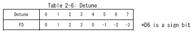
As you can see, this isn't a normal 2's compliment signed value. The detune register uses a primitive sign bit, so you've got a range of -3 to +3, with both -0 and +0, which are equivalent. In order to use the detune data, we need to separate the sign bit, leaving us with just the lower 2 bits of the register value, and a flag indicating whether the detune is positive or negative.
With both the key-code calculated, and the detune data interpreted, we now need to calculate the detune adjustment itself. For that, we need to use a table. The YM2608 manual also lists a detune table on page 26, which looks a little something like this:
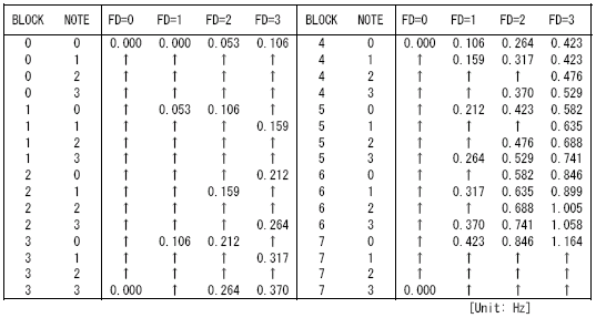
Note that where this table lists "block" and "note" down the side, what those really correspond with is the key-code we just calculated. "Block" is of course the upper 3 bits of the key-code, while "Note" is the lower 2 bits of the key code, so essentially the table is listing detune values in order for a key-code from 0 to 0x1F. The other index used here is the lower 2 bits of the detune register data, which we separated above, so we've got a multi-dimensional array of [32][4].
These values that are given in the detune table are accurate. Unfortunately, they're given in Hz. We need to convert these values into actual numbers we can add to our frequency increment value in order to apply them. In fact, that's not too tricky. Looking at the detune table, we can see that every value detune value is given as a multiple of 0.053Hz. There's a little but of rounding coming into play for the higher values, but basically they're all a common factor of 0.053. This tells us that the resolution of the detune table only allows minimum adjustments to the increment value by steps of 0.053Hz, and we can break each value in the table down into a multiple of this adjustment. Now we just need to calculate what fnum value corresponds with a single step in the detune table. For that, we can use the frequency formula given earlier, to calculate the fnum value needed to produce an output of the specified frequency. Taking out the block adjustment which doesn't apply here, the fnum calculation for a frequency of 0.053Hz is as follows:
fnum = 144 * 0.053 * 2^20 / 8000000 = 1 (rounded)
So basically, we've just confirmed a single step in the detune corresponds with a single number adjustment to the frequency increment value. Note that we used a clock frequency of 8MHz in this calculation, as all the values given in the YM2608 manual have been calculated assuming a clock rate of 8MHz.
After converting all those numbers in the detune table from Hz to fnum values, you get something a little like this:
Code: Select all
//     Detune        Key-Code
//   0  1  2  3
    {0, 0, 1, 2},   //0  (0x00)
    {0, 0, 1, 2},   //1  (0x01)
    {0, 0, 1, 2},   //2  (0x02)
    {0, 0, 1, 2},   //3  (0x03)
    {0, 1, 2, 2},   //4  (0x04)
    {0, 1, 2, 3},   //5  (0x05)
    {0, 1, 2, 3},   //6  (0x06)
    {0, 1, 2, 3},   //7  (0x07)
    {0, 1, 2, 4},   //8  (0x08)
    {0, 1, 3, 4},   //9  (0x09)
    {0, 1, 3, 4},   //10 (0x0A)
    {0, 1, 3, 5},   //11 (0x0B)
    {0, 2, 4, 5},   //12 (0x0C)
    {0, 2, 4, 6},   //13 (0x0D)
    {0, 2, 4, 6},   //14 (0x0E)
    {0, 2, 5, 7},   //15 (0x0F)
    {0, 2, 5, 8},   //16 (0x10)
    {0, 3, 6, 8},   //17 (0x11)
    {0, 3, 6, 9},   //18 (0x12)
    {0, 3, 7,10},   //19 (0x13)
    {0, 4, 8,11},   //20 (0x14)
    {0, 4, 8,12},   //21 (0x15)
    {0, 4, 9,13},   //22 (0x16)
    {0, 5,10,14},   //23 (0x17)
    {0, 5,11,16},   //24 (0x18)
    {0, 6,12,17},   //25 (0x19)
    {0, 6,13,19},   //26 (0x1A)
    {0, 7,14,20},   //27 (0x1B)
    {0, 8,16,22},   //28 (0x1C)
    {0, 8,16,22},   //29 (0x1D)
    {0, 8,16,22},   //30 (0x1E)
    {0, 8,16,22}};  //31 (0x1F)
So we can see the maximum adjustment that detune will make to the increment value is 22.
Using the lookup table above, we're able to calculate phase adjustment values for detune, but we still have to factor in the sign bit from the detune register. For positive detune adjustments, the numbers from the table can be directly added to the intermediate fnum result. When the sign bit is set however, we have to calculate the 2's compliment of the detune value before we can add it to fnum, and this 2's compliment value needs to be sign-extended to a 17-bit value.
To give some examples about how detune is applied, consider a case where fnum is 0x100 and block is 5. In this case, we perform the following operation:
0x100 << 4 = 0x1000
So, our intermediate 17-bit fnum result before applying detune is 0x1000. The next step is to calculate the key-code value, which from a block of 5 and fnum of 0x100, is 0x14. Let's say the detune register data is 0x3. When we look at the table above, a detune value of 3 and a key-code of 0x14 gives a detune adjustment value of 11(0xB). So, to apply detune, we simply add that detune adjustment value to the intermediate fnum result:
0x1000 + 0xB = 0x100B
And that's fnum adjusted for detune.
Now consider the case where the detune data is 0x7. In this case, the detune adjustment is -3. First of all, we read the detune adjustment value for +3 from the table, which is of course still 11(0xB). We need to calculate the 2's compliment of this number now, in a register size of 17-bit, like so:
0 - 0xB = 0x1FFF5 (17-bit)
We now add that inverted detune value to the intermediate fnum result, and cap the result to 17-bits:
0x1000 + 0x1FFF5 = 0xFF5 (17-bit)
Since 0x1000 - 0xB = 0xFF5, we can see we've obtained the correct result.
It's up to you how you want to implement this in code, whether you use 2's compliment and addition, or just use subtraction for negative values, what you represent using signed and unsigned types, etc, but these are the results you need to get at the end. There's some further discussion of detune in the next section.
3. Applying the frequency multiplier
This step is fairly simple. The multiple register provides a 4-bit value to the phase generator. This 4-bit value specifies a multiplier for the frequency, which in real terms means it's a multiplier for the frequency increment value. There's another good table in the YM2608 manual which shows the multiplier each possible value of the multiple register applies to the frequency increment value:
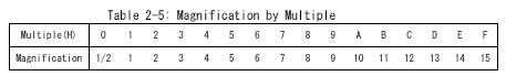
You can see from this table that the multiple register data is simply directly multiplied with the frequency increment value, except for the special case of 0 where it acts as a 0.5 multiplier, or in other words, it halves the frequency increment.
For an example of how the multiplier is applied, consider a case where fnum is 0x1FF and block is 4. From the first stage of the process, we perform the following operation:
0x1FF << 3 = 0xFF8
So, the intermediate 17-bit frequency increment value is 0xFF8. Skipping past detune, let's say the multiple register is loaded with the value 0x8. Looking at the table above, that means the multiplier is 8, so:
0xFF8 * 8 = 0x7FC0
So, our final frequency increment value in this case is 0x7FC0, after the multiplier has been applied. If the multiple data was 0, our multiplier would be 0.5 instead, so:
0xFF8 * 0.5 = 0x7FC
In code, you'll probably want to implement the 0.5 multiplier special case as a simple shift down by 1.
If you correctly apply these main frequency calculation steps, you'll be able to calculate the correct phase increment values for each update. All you've got to do now is add this phase increment value to the stored 20-bit phase value for each operator on each update cycle, and you've got a working phase generator. There is a special case to consider when implementing the phase generator however, which is covered in the next section.
Detune overflow:
The detune setting allows a negative detune value to be applied, which will subtract a small frequency adjustment from the supplied fnum. This begs the question, what happens when fnum is smaller than the number the detune setting is subtracting? The answer is, you get an overflow. The register size at the time the detune value is applied is 17-bit, so if detune attempted to subtract a value of 1 from an fnum of 0, the result would be 0x1FFFF.
You can't get an overflow when detune is positive, as the max output from the shift step is 0x1FFC0 (0x7FF<<6), and the max value we add through detune is 0x16(22), giving a combined total of 0x1FFD6. As you can see, you can actually slightly exceed the maximum intermediate frequency you could normally obtain with fnum and block using detune overflow.
The GEMS sound driver for the Mega Drive has an inbuilt instrument which makes use of detune overflow. A large number of Mega Drive games use the GEMS sound driver, and a significant number of those use this instrument, so if you're working on a Mega Drive emulator, you'll get bad sound in a lot of games unless detune overflow is implemented correctly.
There's actually a second point in the frequency increment calculation where an overflow can occur, and that's when the frequency multiplier is applied. The input to the multiplier is 17-bit, the output from the multiplier is 20-bit, but when you multiply the maximum 17-bit input (0x1FFFF) by the maximum multiplier value (15), you get a result of 0x1DFFF1, which is well over the maximum 20-bit output of 0xFFFFF. This upper bit of data is lost, so an output of 0x1DFFF1 is equivalent to 0xDFFF1. You shouldn't have to do anything special to handle multiplier overflow however, as the phase counter itself is only 20-bit, so this upper bit is going to be discarded anyway when you add the final frequency increment value to the phase counter.
20-bit or 21-bit?:
After reading the information above, you may wonder if the internal phase counter is really 21-bit. It wouldn't have any radical impact at all if the phase counter was actually 21-bit, and the block register actually only shifted up, rather than shifting down one place when the block data was 0. This is certainly a simpler system to emulate. If you test this on the hardware however, you'll find this is not the case. If the register was really 21-bit, you would still have 11 bits of precision in fnum when block = 0. As it turns out, when block is set to 0, an fnum value of 1 = 0, 3 = 2, etc. This shows that the LSB of fnum is lost when block = 0, which means the phase counter is actually 20-bit. A small sidenote really, but you might be left wondering about this like I was, so I thought I'd mention it.
So yeah, I think that just about covers it. Anyone who worked on adding support for the detune overflow bug might want to doublecheck their implementation. The magic register size is 17-bit. If you're representing frequency numbers properly, all you should have to do is mask your increment value to a 17-bit result before applying the frequency multiplier.