Anyone happen to have a simple diagram of the 74HC157 interfacing with the controller port on the megadrive?
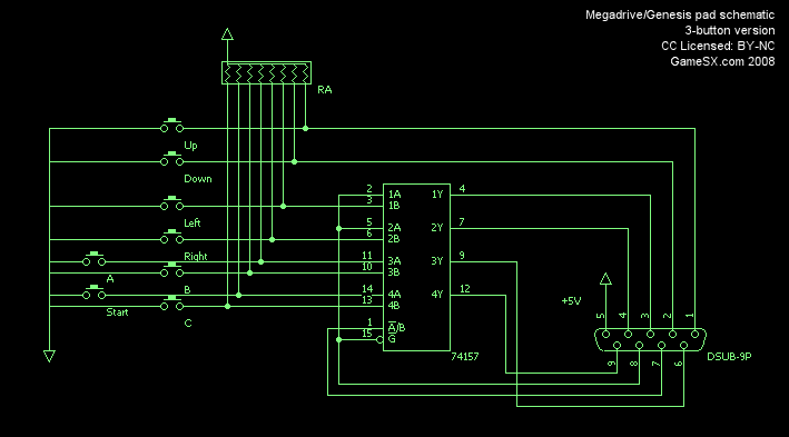
Ive found one here but its somewhat confusing and appears that there may be what looks like an extra line(3a) just after the pin listed for the dpad right "button" (2b)
http://gamesx.com/wiki/lib/exe/fetch.ph ... ematic.png
I feel like everything else looks fine though.
Anyone have a cleaner less sketchy diagram that may clearly define the schematic?
74HC157 To controller port pinouts
-
Mask of Destiny
- Very interested
- Posts: 616
- Joined: Thu Nov 30, 2006 6:30 am
Re: 74HC157 To controller port pinouts
I'd have to check some documentation to be sure, but nothing seems wrong on that schematic. Labels are just a bit messy. 3A on the 74157 is connected to the A button, 3B is the B button, 4A is start and 4B is C.
Re: 74HC157 To controller port pinouts
And for what matters, two inputs should be grounded (detecting 00 for left/right when TH is low is how you can tell that a controller is connected)
Sik is pronounced as "seek", not as "sick".
-
HardWareMan
- Very interested
- Posts: 745
- Joined: Sat Dec 15, 2007 7:49 am
- Location: Kazakhstan, Pavlodar
Re: 74HC157 To controller port pinouts
Labels are below what they labeling. That's is the key.
Re: 74HC157 To controller port pinouts
Thanks guys,
Needed a second set of eyes on that.
Needed a second set of eyes on that.
Re: 74HC157 To controller port pinouts
I was looking at the diagram again and found something else interesting.
Im assuming the values listed on the chip (a1,a2....) are somewhat incorrect as well?
Comparing this to a standard 74hc157 chip im finding that the pin numbers the schematic above lists vs what the pinout of the 74hc157 chip are not matching entirely.
For instance, pin 2 (a1 listed on schematic). When looking at 74hc157 pinout, pin 2 is a0. It almost looks as if the author labeled a1-a4 when it should have started at a0-a3?
Any other opinions?
Re: 74HC157 To controller port pinouts
pretty old and crappy, but does this one help you ?
http://gendev.spritesmind.net/page-p_joy3.html
http://gendev.spritesmind.net/page-p_joy3.html
Re: 74HC157 To controller port pinouts
Thank you very much for that. That helps quite a bit and is much better than the diagram i was using.
Im building a custom controller circuit for a project and just needed something fairly well labeled and this definately does the job.
Thanks again!!
Im building a custom controller circuit for a project and just needed something fairly well labeled and this definately does the job.
Thanks again!!